Device and method for visualization of fluorophores

a fluorophores and fluorescence technology, applied in the direction of fluorescence/phosphorescence, analysis by material excitation, instruments, etc., can solve the problems of limiting the applicability of the method used to detect the fluorescence emitted by biological molecules or associated fluorophores, complex techniques or expensive apparatus, and the lack of simple methods for the dynamic study of the three-dimensional structure of biological molecules

Active Publication Date: 2021-04-20
AMPLYUS LLC
View PDF2 Cites 0 Cited by
  • Summary
  • Abstract
  • Description
  • Claims
  • Application Information

AI Technical Summary

Benefits of technology

The patent describes an apparatus that uses a thermally-controlled device to change the temperature of certain parts of the system by controlling how much light it emits when heated up or cool down. This allows for monitoring changes in fluorescences caused by these devices during operation.

Problems solved by technology

The technical problem addressed in this patent text relates to developing a cheap and efficient way to measure and quantify biological molecules like DNA and RNAs without complicated procedures or expensive equipment. This would allow us to better understand how these molecules function within cells and organisms, potentially leading to new applications in fields ranging from medicine to biotechnology.

Method used


Image

  • Device and method for visualization of fluorophores
  • Device and method for visualization of fluorophores
  • Device and method for visualization of fluorophores

Examples


Embodiment Construction

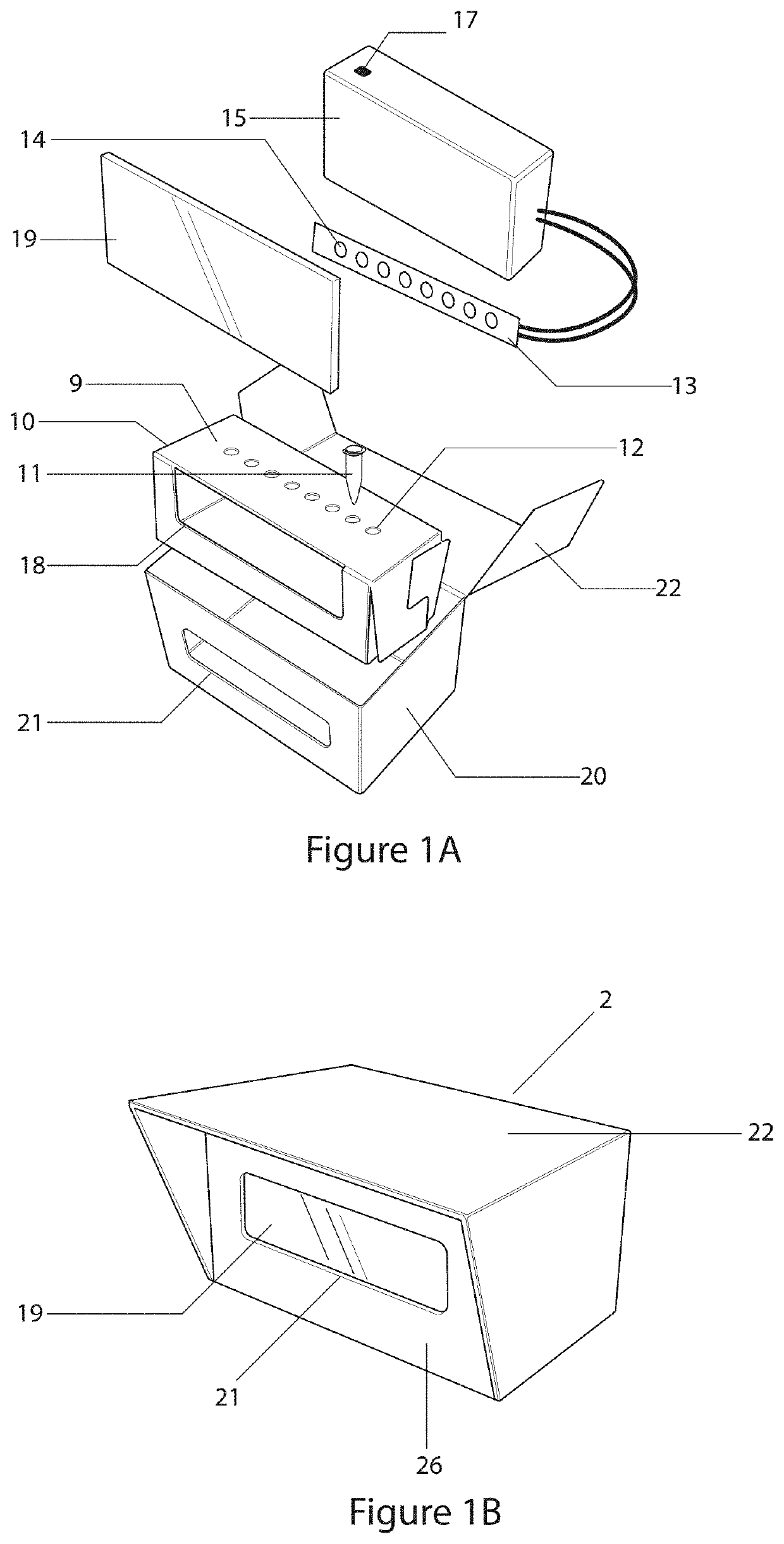
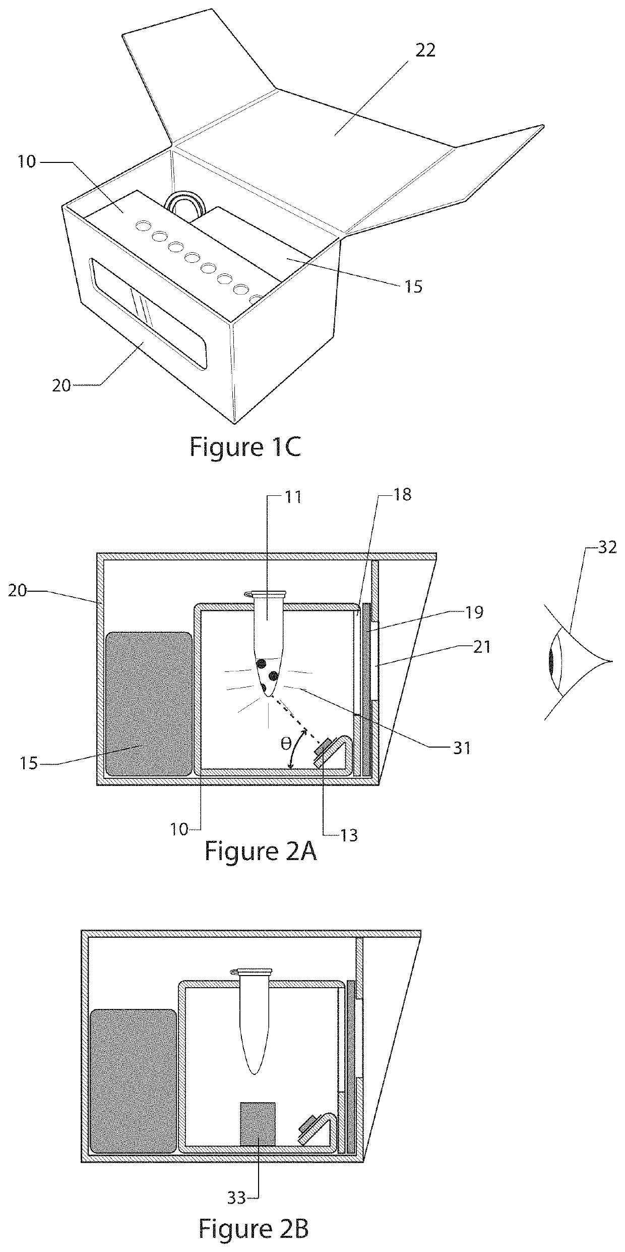
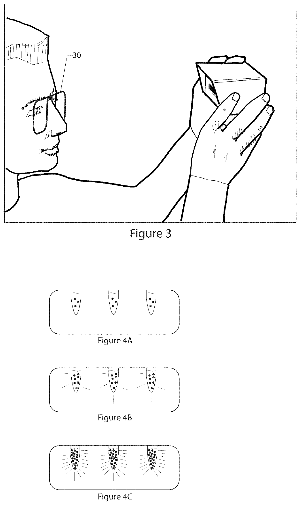
[0004]In accordance with one embodiment of the invention, a fluorophore visualization device is described for the naked eye visualization and / or imaging of fluorophores. The device includes a first chamber defined by a set of walls including a horizontally disposed top, a front wall, and a floor. The walls of the chamber are opaque. The top wall of the chamber has one or more openings for removably receiving one or more test tubes. The test tubes include fluorophore containing compositions, which emit light at longer wavelengths upon excitation by light at shorter wavelengths. The front wall of the chamber includes a first window positioned so that the test tubes can be observed through the window. A light source providing excitation light is positioned within the chamber. The excitation light excites the fluorophores, causing them to emit light, which can be seen through the window, thereby enabling the fluorophores to be observed by the naked eye. The light source is so positioned


PUM


Abstract

A device and method are described for the naked eye visualization of fluorophores. The device has a light source capable of exciting fluorophores, a rack to receive one or more fluorophores and a window through which test tubes can be observed. The method provides a means for inferring the conformational state of molecules from the amount of fluorescence emitted by the fluorophores.

Description


Claims


Application Information

Patent Timeline
Owner AMPLYUS LLC
Why Eureka
Try Eureka