Bow fishing illumination system

Active Publication Date: 2021-12-28
BEALL CHRISTOPHER J
View PDF83 Cites 0 Cited by
  • Summary
  • Abstract
  • Description
  • Claims
  • Application Information

AI Technical Summary

Benefits of technology

[0012]In accordance with other aspects of the present invention the joystick has a handle that includes a trigger button for controlling a propeller between on and off position in order to control the motion of the vessel, and a speed button that controls a hi

Problems solved by technology

For illumination apparatus there presently exist several items, but these existing devices are ineffective.
As far as existing joysticks are concerned, althoug

Method used


Image

  • Bow fishing illumination system
  • Bow fishing illumination system
  • Bow fishing illumination system

Examples


Embodiment Construction

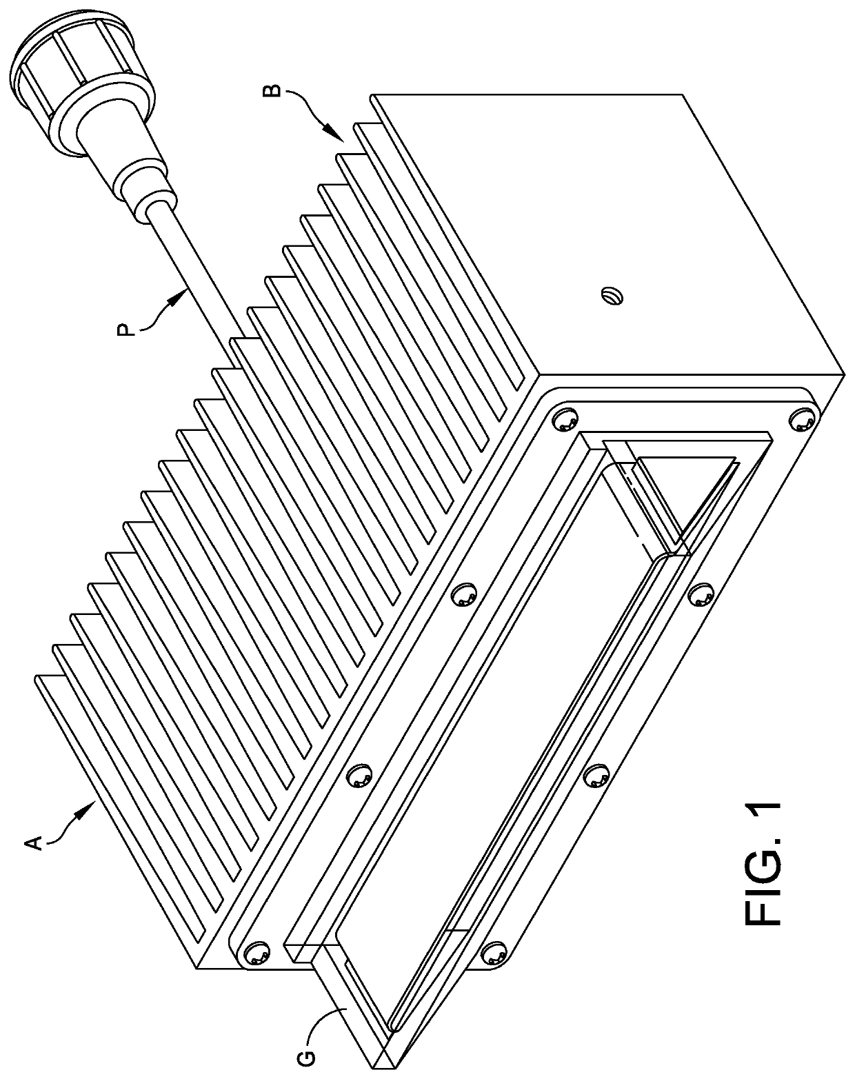
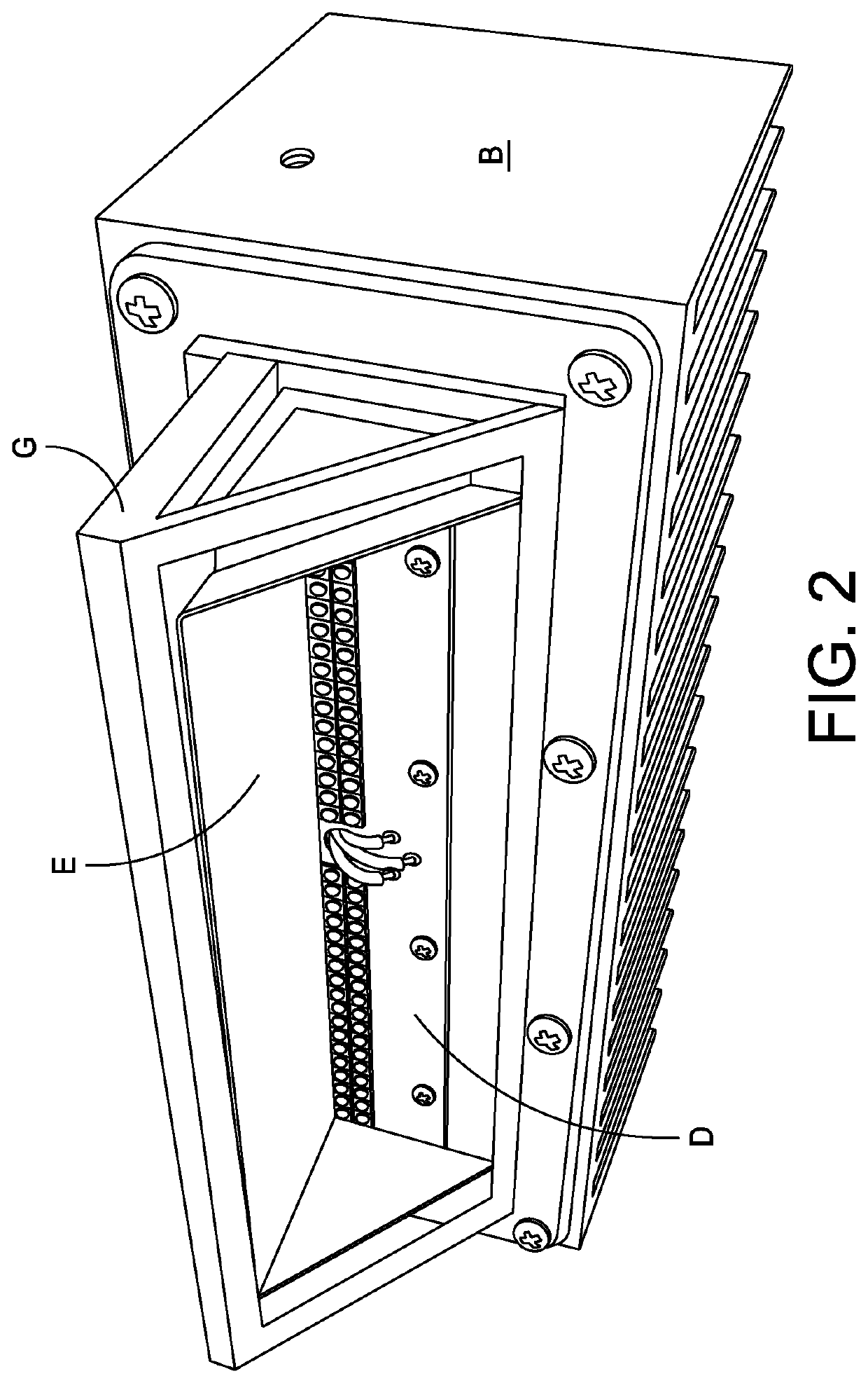
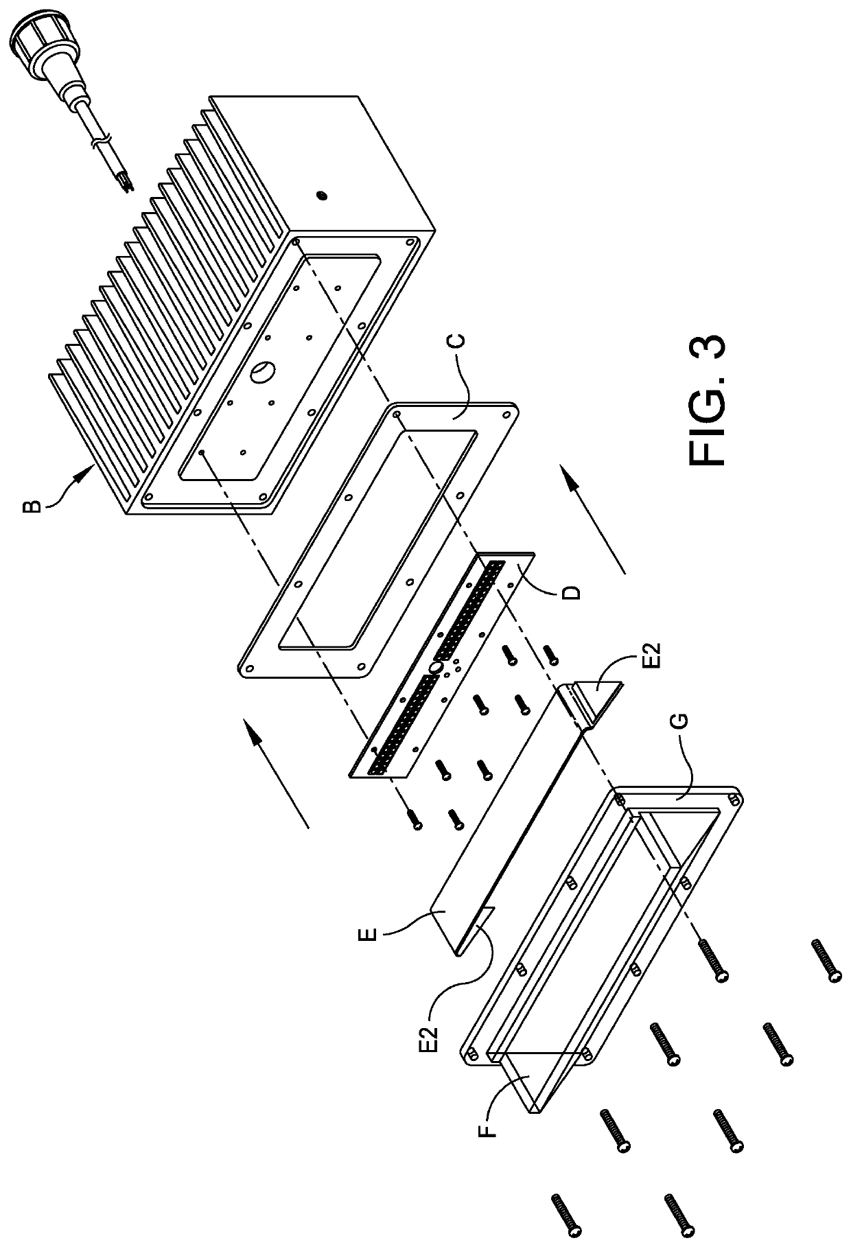
[0037]As part of this description refer to FIGS. 1-22 that provide further specific details of the system of the present invention. In this regard, FIGS. 1-17 describe the system A which includes a heat sink B, a gasket C, a printed circuit board D for supporting the LEDs, a reflector E and a main translucent plastic piece F. FIGS. 12-17 describe the overall system. FIGS. 18-22 relate to the joystick controller.

[0038]There are several important aspects to the present invention which include the fact that a reflector is employed so that the light rays are directed toward the water and not dispersed in multiple directions. Another feature of the present invention is the use of separate LED banks or sets. This includes one bank or set B1 comprised of white LEDs and a parallel second bank or set B2 that is comprised of amber LEDs. In this regard, refer to FIGS. 3 and 9 of the drawing. The banks B1 and B2 can be organized with the bank B1 either on the top or on the bottom relative to bank


PUM


Abstract

A bow fishing illumination system for support on a vessel and including a bank of illumination modules that extend outboard of the vessel so as to illuminate a water surface about the vessel. The bank of illumination modules includes a support housing, a reflective member disposed with the support housing and having a reflective surface, and an array of LED's disposed with the support housing in a manner to have their light beam extend away from the support housing. The array of LED's includes a plurality of LED's that are arranged in at least one spaced apart linear array. A joystick controller is mounted on the vessel and includes a base used for the purpose of mounting the joystick controller, a joystick mounted to the base, a first button on the base that is separate from the joystick for controlling a locking feature, and a second button on the base that is separate from the joystick for controlling an auto pilot feature.

Description


Claims


Application Information

Patent Timeline
Owner BEALL CHRISTOPHER J
Why Eureka
Try Eureka