Fan motor speed control circuit

Active Publication Date: 2005-01-27
DELTA ELECTRONICS INC
View PDF6 Cites 13 Cited by
  • Summary
  • Abstract
  • Description
  • Claims
  • Application Information

AI Technical Summary

Benefits of technology

[0010] The advantage of this invention is to reduce the vibration degree and noise problem occurred

Problems solved by technology

A conventional fan motor rotation speed control circuit cannot avoid the noise problem caused by th

Method used


Image

  • Fan motor speed control circuit
  • Fan motor speed control circuit
  • Fan motor speed control circuit

Examples


Embodiment Construction

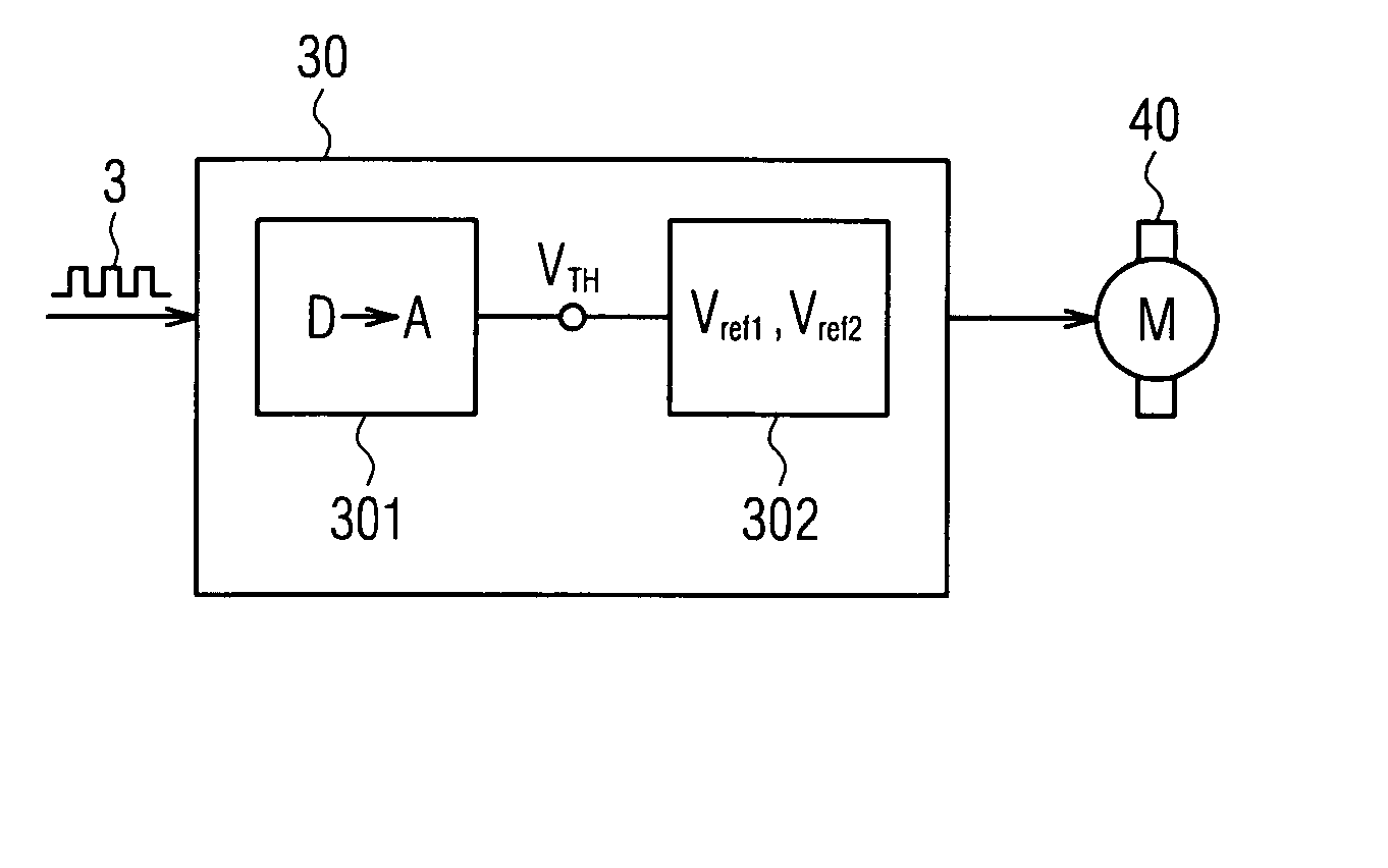
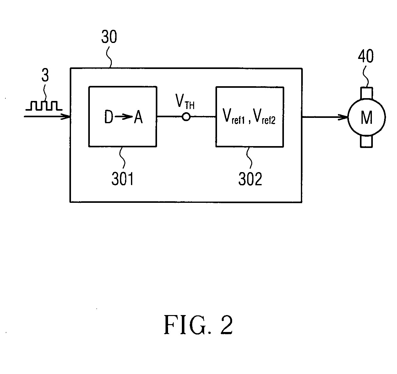
[0019] Referring to FIG. 2, a fan motor speed control circuit 30 in accordance with the invention comprises a digital / analog converting unit 301 and a driving unit 302. The digital / analog converting unit 301 is used for converting an inputted PWM digital signal 3 into an analog signal such as a voltage signal. The driving unit 302 takes the analog signal and compares it with two predetermined voltages Vref1 and Vref2 set by the driving unit. After that, a digital signal representing the comparison result is used to control the rotation speed of the fan motor 40.

[0020] The fan motor speed control circuit according to one embodiment of the invention is shown in FIG. 3A. In this embodiment, a digital / analog converting circuit 22 is employed as a digital / analog converting unit, and a drive IC 23 is employed as a driving unit. In this embodiment, the digital / analog converting circuit 22 is mainly composed of a transistor 221, a diode 222, a capacitor 223, and a plurality of resis


PUM


Abstract

A fan motor speed control circuit is disclosed. The circuit includes a digital/analog converting unit and a driving unit. The digital/analog converting unit takes charge of receiving a pulse width modulation (PWM) signal and converting it into a voltage signal. The driving unit is connected with the digital/analog converting unit in series for receiving the voltage signal, while the driving unit provides a first predetermined voltage level and a second predetermined voltage level as references. The fan motor is kept to run with a low constant rotation speed when the voltage signal level is higher than the first predetermined voltage level, with a full constant rotation speed when the voltage signal level is lower than the second predetermined voltage level, and with a variable rotation speed when the voltage signal level is lower than the first predetermined voltage level and higher than the second predetermined voltage level.

Description


Claims


Application Information

Patent Timeline
Owner DELTA ELECTRONICS INC
Why Eureka
Try Eureka