Apparatus and method for limiting the re-use of fiber optic, laser energy delivery devices

Inactive Publication Date: 2005-05-26
TRIMEDYNE
View PDF15 Cites 10 Cited by
  • Summary
  • Abstract
  • Description
  • Claims
  • Application Information

AI Technical Summary

Benefits of technology

[0022] A further objective is to provide an invention capable of preventing the remov

Problems solved by technology

This allows an optical fiber to be re-used up to 50 or more times. Stresses encountered in such multiple uses can cause the optical fiber to crack at some point along its length and emit laser energy in an unpredictable direction, placing the patient and the operating room personnel at risk.
There are no stripping devices commonly available in the medical field able to strip or clip-off a portion of a sleeve with such a large outside diameter.
Clearly, any other number of sections of the optical fiber can be marked for removal, and reuse of the device will be limited thereby.
The quartz or fused silica core of the assembly is not affected by the transmission of a moderate amount of laser energy, but may crack or shatter if exposed to excessive laser energy over time and is bent during use.
Backscatter of light energy from tissue has also been f

Method used


Image

  • Apparatus and method for limiting the re-use of fiber optic, laser energy delivery devices
  • Apparatus and method for limiting the re-use of fiber optic, laser energy delivery devices
  • Apparatus and method for limiting the re-use of fiber optic, laser energy delivery devices

Examples


Example

[0030] The above described drawing figures illustrate the invention in at least one of its preferred embodiments, which is further defined in detail in the following description. Those having ordinary skill in the art may be able to make alterations and modifications in the present invention without departing from its spirit and scope. Therefore, it must be understood that the illustrated embodiments have been set forth only for the purposes of example and that they should not be taken as limiting the invention as defined in the following.

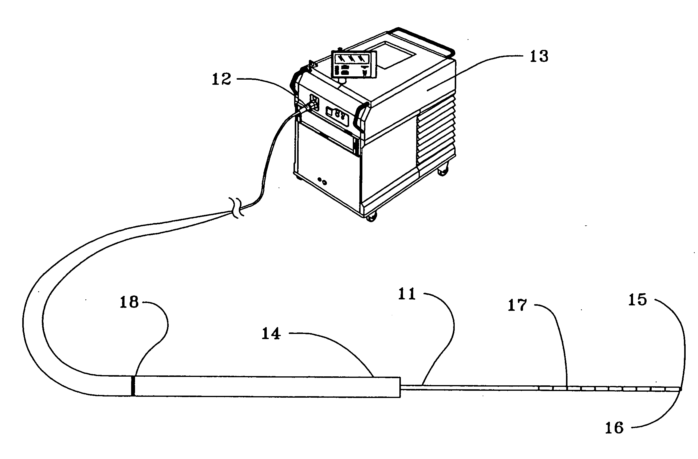
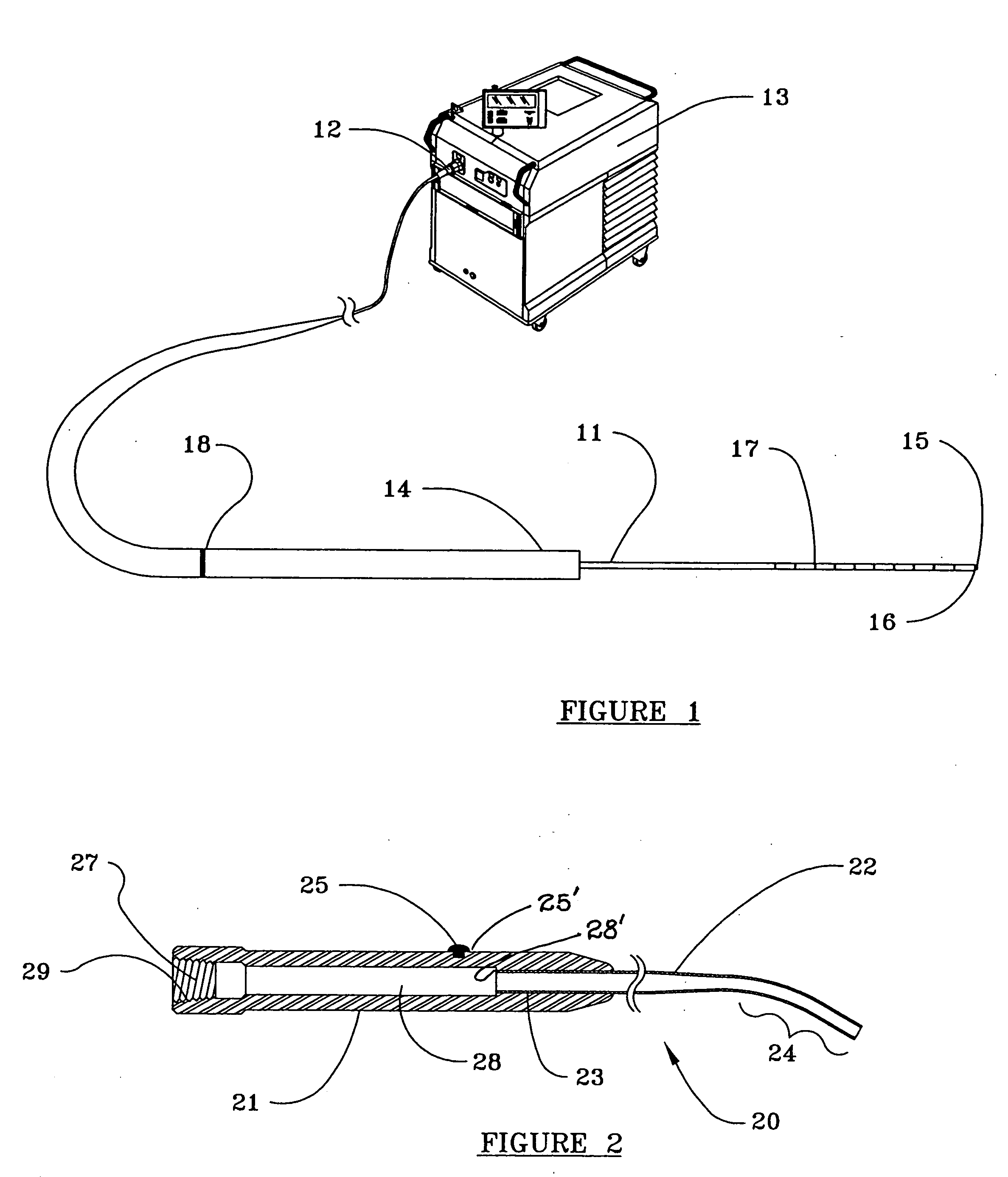
[0031] As seen in FIG. 1, the proximal end of optical fiber 11 is fixedly attached within connector 12 and optically coupled to laser 13. Plastic or metal sleeve 14, which preferably has an outside diameter of at least about 2.0 mm, is attached by an adhesive, heat shrinking, crimping or other means, to a portion of the body of optical fiber 11, preferably extending from connector 12 to the point at which optical fiber 11 emerges from the distal end


PUM


Abstract

An apparatus for limiting the number of times a fiber-optic, laser energy delivery device can be reused consists of a sleeve attached about a portion of the body of an optical fiber and a handpiece and attached hollow cannula through which the portion of the optical fiber not encased in the sleeve extends. A compression means, whose aperture, when fully closed, has an inside diameter smaller than the outside diameter of the sleeve, but greater than the outside diameter of optical fibers generally available in the medical field, is provided.

Description


Claims


Application Information

Patent Timeline
Owner TRIMEDYNE
Why Eureka
Try Eureka