Cellular radio communication system cellular radio communication method and rake reception method
- Summary
- Abstract
- Description
- Claims
- Application Information
AI Technical Summary
Benefits of technology
Problems solved by technology
Method used
Image

Examples
first embodiment
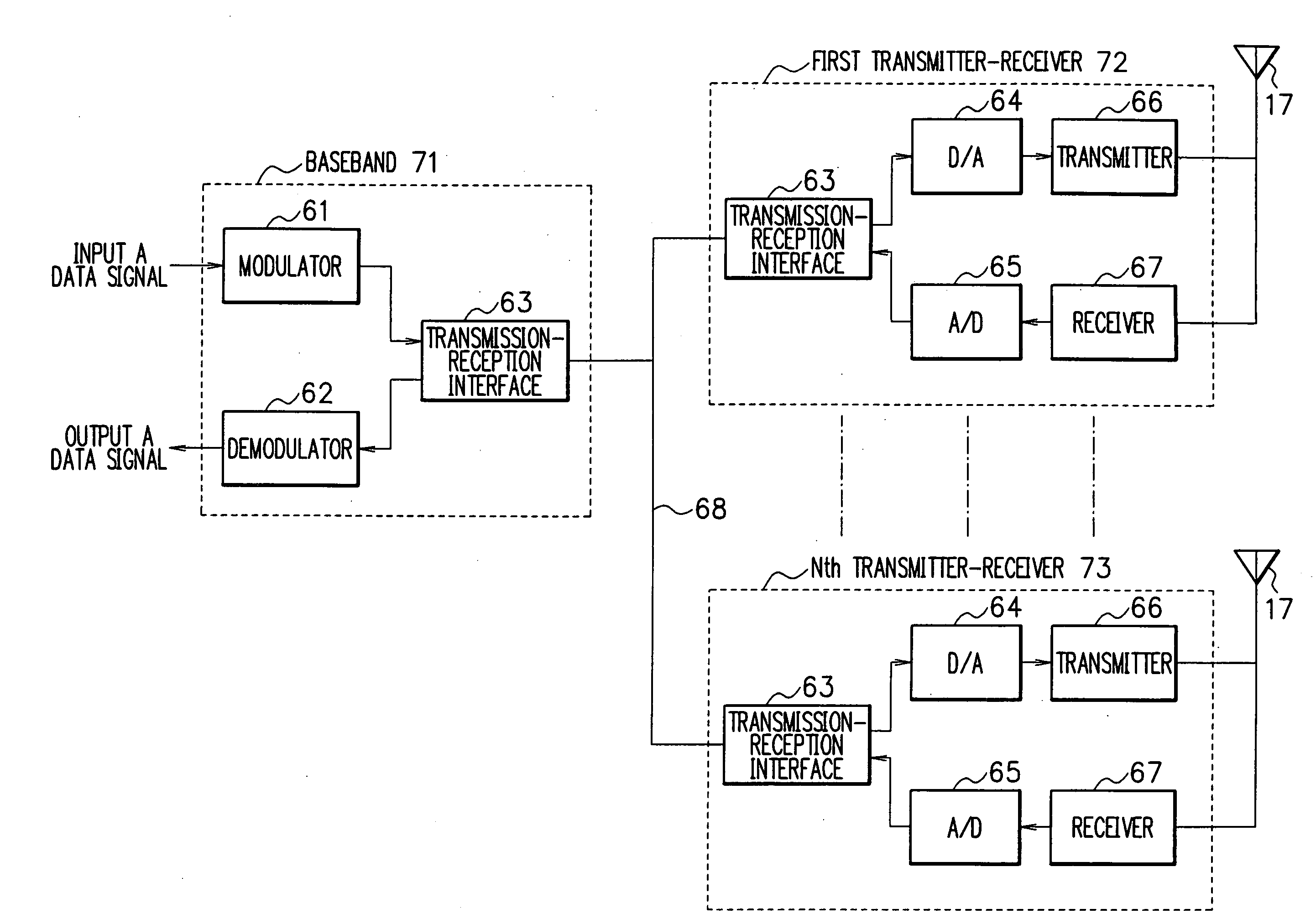
[0026]FIG. 4 is a block diagram showing the structure of a base station according to the present invention. Referring to FIG. 4, each of N pieces of base stations is comprised of a baseband 71 and first to Nth transmitter-receivers connected via a transmission line 68. The baseband 71 comprises a modulator 61, a demodulator 62 and a transmission-reception interface 63.
[0027] Each transmitter-receivers is comprised of a digital-to-analog converter 64, an analog-to-digital converter 65, a transmitter 66, a receiver 67 and a transmission-reception interface 63. One baseband carries out baseband operations for the first to Nth transmitter-receivers.
[0028] The baseband 71 performs digital processing including CPU software processing by using a digital signal. That is, the baseband 71 performs time-sharing processing or parallel processing by one or more digital processing circuits.
[0029] The modulator 61 performs modulation by a modulation method such as PSK (Phase-Shift Keying), QAM (Qua
second embodiment
[0035]FIG. 5 is a block diagram showing a base station according to the present invention. In FIG. 5, first to Mth basebands and first to Nth transmitter-receivers are connected through transmission-reception interfaces 63 by a transmission line 68. Examples of the transmission line 68 include a transmission line time-shared by the first to Mth basebands and the first to Nth transmitter-receivers for digital signal transmission such as the Internet using TCP / IP protocol, and an optical transmission line in which digital signals to / from the first to Mth basebands and the first to Nth transmitter-receivers are time-division multiplexed or wavelength multiplexed.
[0036] Referring to FIG. 5, a description will be given of the operation of the base station according to the second embodiment. The basebands and the transmitter-receivers are connected via the transmission line 68. Each baseband takes charge of a modulation-demodulation processing for the plural transmitter-receivers as in t
third embodiment
[0037]FIG. 6 is a block diagram showing the detailed structure of a baseband using CDMA radio signals according to the present invention. A modulator 87 comprises the first modulator 81 which performs modulation such as PSK, QAM, and OFDM, and a diffuser 82. A demodulator 88 comprises a back diffuser 85, a first demodulator 84 which performs demodulation and a rake receiver 86.
[0038] Referring to FIG. 6, a description will be made of the operation of the baseband 75 using CDMA radio signals. The modulator 87 performs modulation such as PSK, QAM, and OFDM at the first modulator 81, and then performs diffusion at the diffuser 82 to produce a CDMA signal. The CDMA signal is sent to a transmitter-receiver by the transmission-reception interface 63 via the transmission line 68.
[0039] On the other hand, the CDMA signal received by the transmitter-receiver is sent to the demodulator 88 by the transmission-reception interface 63 of the baseband 75 via the transmission line 68. The demodulator
PUM
 Abstract
Description
Claims
Application Information
 - R&D Engineer
- R&D Manager
- IP Professional
- Industry Leading Data Capabilities
- Powerful AI technology
- Patent DNA Extraction
Browse by: Latest US Patents, China's latest patents, Technical Efficacy Thesaurus, Application Domain, Technology Topic.
© 2024 PatSnap. All rights reserved.Legal|Privacy policy|Modern Slavery Act Transparency Statement|Sitemap