Steering wheel damper

Inactive Publication Date: 2005-07-21
AUTOLIV ASP INC
View PDF25 Cites 9 Cited by
  • Summary
  • Abstract
  • Description
  • Claims
  • Application Information

AI Technical Summary

Benefits of technology

[0015] The present invention has been developed in response to the present state of the art, and, in particular, in response to problems and needs in the art that have not yet been fully solved by currently available steering wheel dampers. More specifically, the present invention provides a cost-effective s

Problems solved by technology

The movement of these components produces vibrations, which can be transferred throughout the vehicle.
The engine, for example, can be a source of significant vehicle vibrations.
Unfortunately, these alterations may adversely affect fuel economy or the performance of the vehicle.
An additional source of vehicle vibration is contact between the vehicle and the driving surface.
For example, vehicle speed, aberrations in the driving surface, wheel alignment, and uneven tire wear can significantly impact the vibrations generated in the vehicle.
Nevertheless, problems still persist and vibration control is an ongoing concern for automobile manufacturers.
When the frequency of the generated vibrations substantially matches the natural resonance frequency of a part of the vehicle, that part vibrates and may cause adjoining or abutting parts to also vibrate.
Such vibrations can cause annoyance to the driver and even premature part failure.
However, these alterations may be expensive and can adversely affect the

Method used


Image

  • Steering wheel damper
  • Steering wheel damper
  • Steering wheel damper

Examples


Example

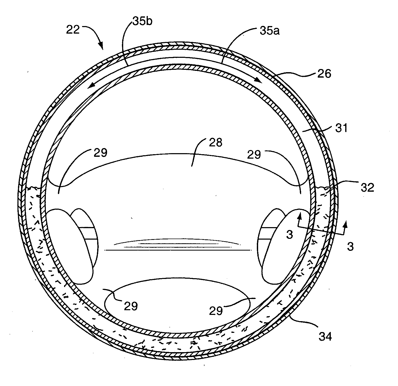
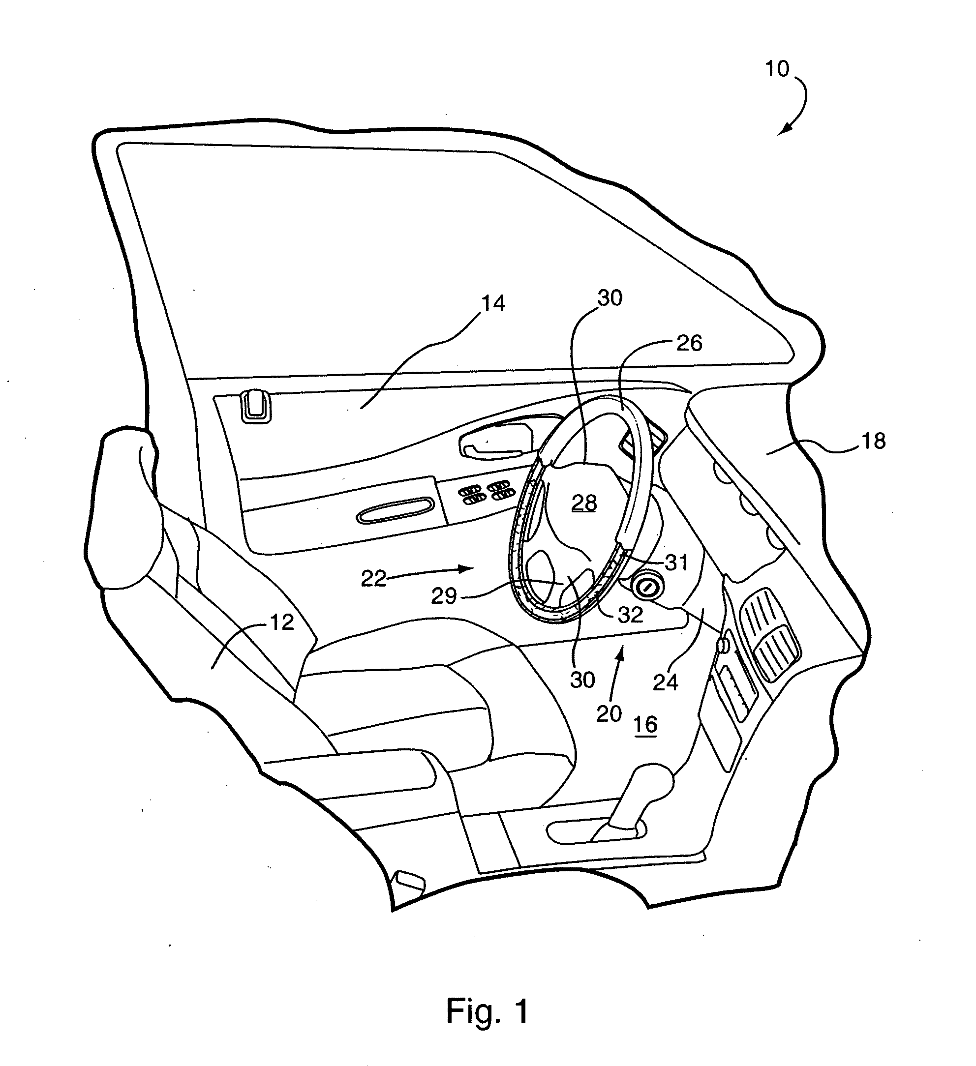
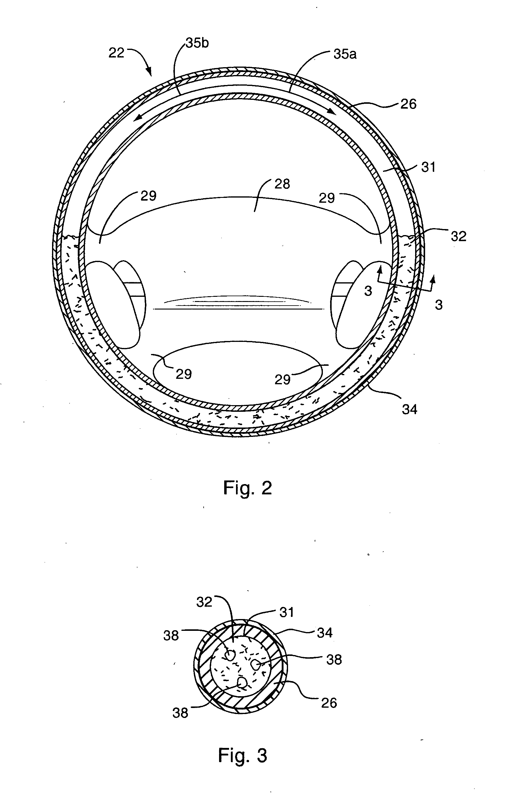
[0037] The preferred embodiments of the invention are now described with reference to FIGS. 1-5, wherein like parts are designated by like numerals throughout. The members of the present invention, as generally described and illustrated in the Figures, may be constructed in a wide variety of configurations. Thus, the following more detailed description of the embodiments of the present invention, as represented in the Figures, is not intended to limit the scope of the invention, as claimed, but is merely representative of presently preferred embodiments of the invention.

[0038] In this application, the phrases “connected to,”“coupled to,” and “in communication with” refer to any form of interaction between two or more entities, including mechanical, electrical, magnetic, electromagnetic, electromechanical and thermal interaction. The phrase “attached to” refers to a form of mechanical coupling that restricts relative translation or rotation between the attached objects. The phrases “pi


PUM


Abstract

A steering wheel having a central member and an outer rim connected to the central member is disclosed. The central member is attachable to a steering column of a vehicle. The outer rim has one or more internal chambers. A fluid, such as antifreeze, is disposed within the internal chamber or chambers. The volume, viscosity, and weight of the fluid is selected to dampen vibrations of the steering wheel caused by operation of the vehicle and/or to achieve a desired inertia level in the steering wheel.

Description


Claims


Application Information

Patent Timeline
Owner AUTOLIV ASP INC
Why Eureka
Try Eureka