Equalizer architecture

a technology of equalizers and components, applied in equalizers, transmission, transmitter/receiver shaping networks, etc., can solve the problems of increasing the probability that the receiver will fail to determine correctly, increasing the probability of bit errors, and placing a so as to achieve high data rates and high computational burden on the components

Inactive Publication Date: 2005-09-15
PHYWORKS
View PDF6 Cites 10 Cited by
  • Summary
  • Abstract
  • Description
  • Claims
  • Application Information

AI Technical Summary

Benefits of technology

The technical effect of this patented technology is that it allows for faster processing of data over multiple channels at once by providing a more efficient way to process these data streams. This means that fewer parts are needed than traditional methods like analog techniques or digital signal processing (DSP).

Problems solved by technology

This patent describes various technical problem addressed in this patent text: The technical problem discussed in the patent text relates to improving the efficiency of digital communication systems by reducing the impact of inter- symbol-interference (ISI) caused by factors like fiber imperfections.

Method used


Image

  • Equalizer architecture
  • Equalizer architecture
  • Equalizer architecture

Examples


Embodiment Construction

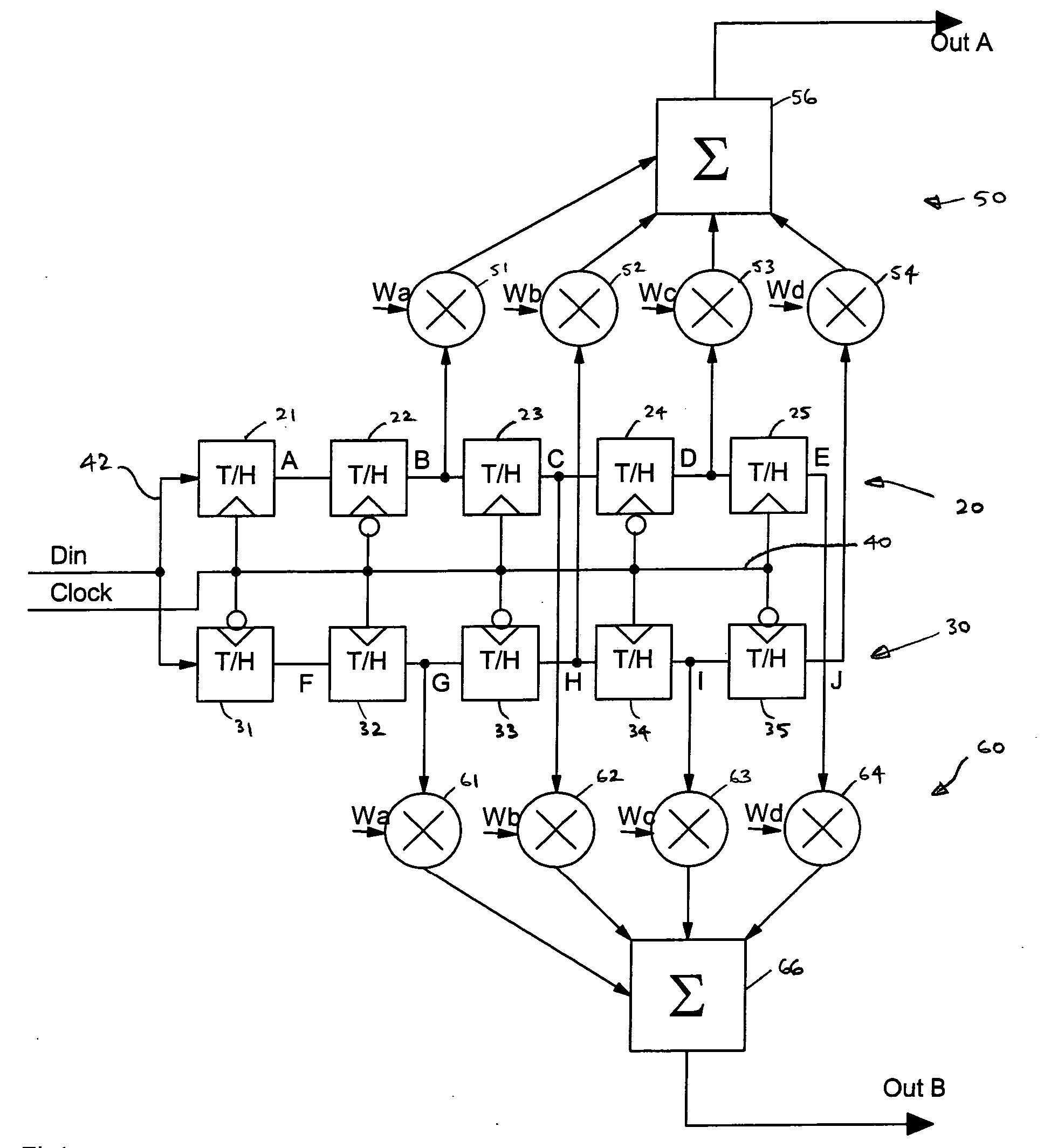
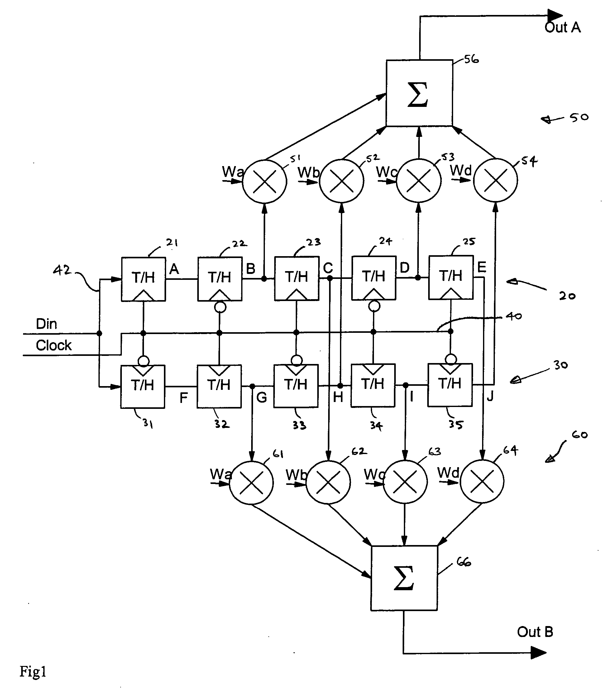
[0019]FIG. 1 is a block schematic diagram of an equalizer in accordance with the present invention, implemented in the form of a finite impulse response filter, divided into two parallel paths.

[0020] Thus, compared with a conventional finite impulse response filter implementation, which includes a tapped delay line, the equalizer of FIG. 1 includes a first tapped delay line 20 and a second tapped delay line 30. In this illustrated embodiment of the invention, the first tapped delay line 20 is made up of five track and hold circuits 21-25, while the second tapped delay line 30 is made up of five track and hold circuits 31-35. However, it will be appreciated that the tapped delay lines may be of any convenient length, depending on the extent to which transmitted bits are spread over multiple bit periods by the time they reach the receiver.

[0021] In this illustrated embodiment of the invention, each of the track and hold circuits 21-25, 31-35 is of a type which is transparent when its c


PUM


Abstract

An equalizer is divided between two tapped delay lines. One half of the sampled data is passed along one delay line, and the other half of the sampled data is passed along the other delay line. Delayed samples are passed to two summing circuits, and the output is formed from the two summing circuits alternately. This structure has the advantage that, by doubling the number of components, each component effectively only needs to operate at half the rate which would be required in a conventional structure. This allows the equalizer to operate successfully with signals at higher data rates.

Description


Claims


Application Information

Patent Timeline
Owner PHYWORKS
Why Eureka
Try Eureka