Fluid ejector having an anisotropic surface chamber etch
- Summary
- Abstract
- Description
- Claims
- Application Information
AI Technical Summary
Problems solved by technology
Method used
Image

Examples
second embodiment
[0129] A second embodiment for forming a region of constriction in the fluid passageways between the nozzle and the ink delivery channel is illustrated in FIGS. 12-16. In this embodiment a pendent protrusion is formed within the chamber to form the region of constriction. In particular, this type of protrusion hangs down from the roof of the chamber (that is, the portion of the multilayer stack comprising the nozzle plate) and extends partway into the chamber. The protrusion is made by filling a pit which will remain adhering to the bottom of the multilayer stack when the fluid chamber is subsequently etched.
[0130]FIG. 12 shows the first step of etching a pit 221 into first surface 211 of silicon substrate 210. The pit 221 may be etched by a variety of isotropic or anisotropic means. However, in this embodiment, it is shown, for example, to be etched by orientation dependent etching. This pit has lateral dimensions I and w, and a depth d which is half the square root of 2 times the sma
first embodiment
[0132]FIG. 14 shows the result of the various processing steps for the multilayer stack 240, a portion of which comprises a nozzle plate 250. It is similar to FIG. 6 for the first embodiment, and similar numbers refer to similar parts, including multilayer stack 240, heater element 251, oxide layer 241, region 242 of oxide which has been removed corresponding to the eventual location of the fluid chamber, sacrificial layer 243, and region of overlap 244 of sacrificial layer on top of the oxide layer. Also shown in FIG. 14 is an island of oxide layer 245 which remains within the eventual chamber location and is deposited over pendent protrusion material 222.
[0133]FIG. 15 illustrates the steps for fabricating the fluid chamber. After the nozzle 252 is formed, both the sacrificial layer 243 and the chamber 213 are etched. If the sacrificial material 243 is a material such as polysilicon, which can be etched at the same time as the fluid chamber, then these two steps may occur simultaneous
fourth embodiment
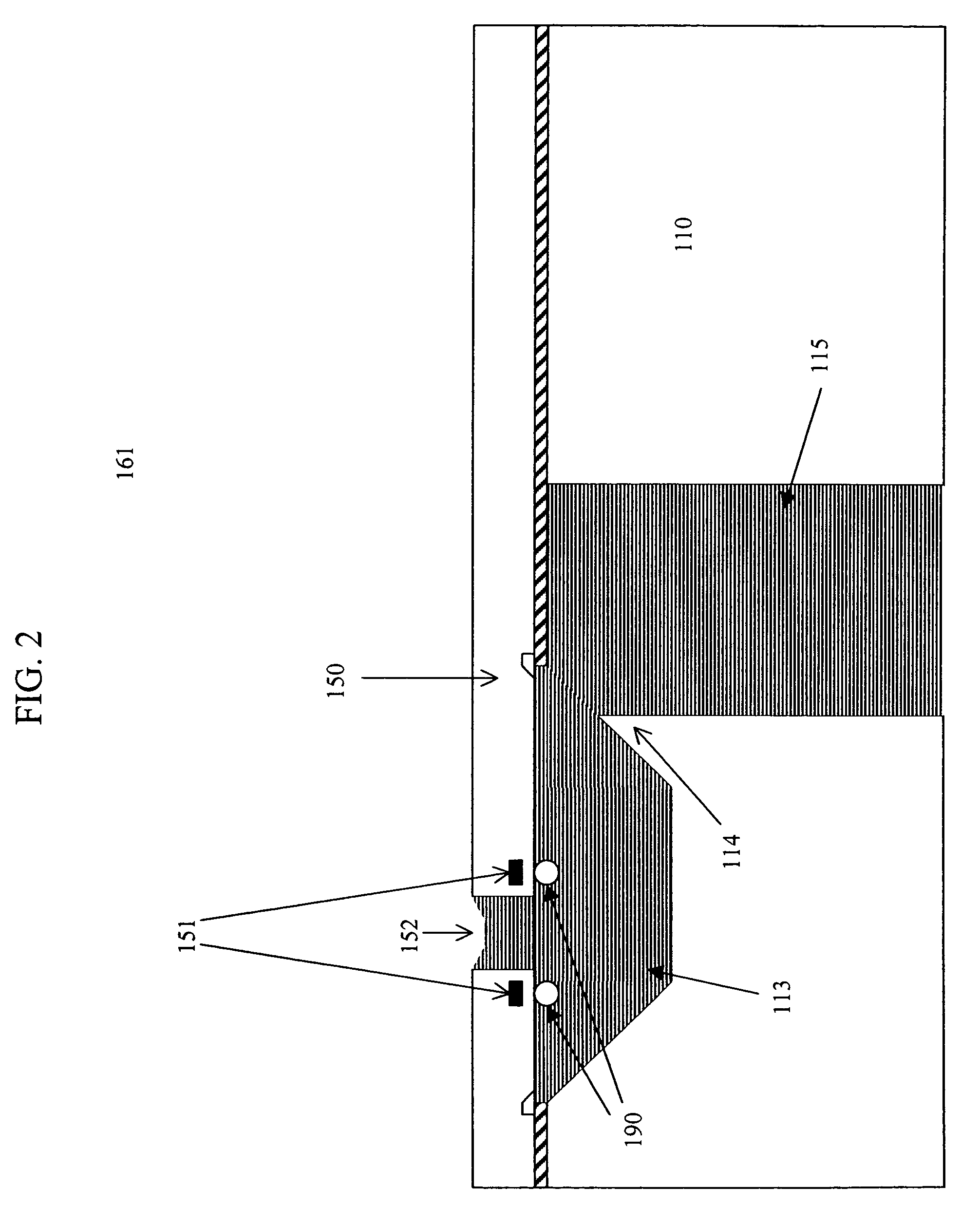
[0154] As in the fourth embodiment, it is desirable (for adequately fast fluid refill during operation) to enlarge the connecting regions between the fluid chamber and the stages of the impedance channel. In FIG. 34 an isotropic etch step has been performed, for example by allowing an etching gas such as SF6 or XeF2 to enter the nozzle region 552 for a predetermined period of time, and thereby etch regions of exposed silicon. As a result, fluid chamber 513 and both stages of the impedance channel 519a and 519b are enlarged somewhat.
[0155]FIG. 35 shows the formation of the fluid delivery channel 515 by DRIE from the backside of the silicon substrate. Its point of intersection with the second stage 519b of the impedance channel is shown as occurring at a location where the second stage 519b is at its full depth rather than where the end wall is sloping. However, it may be appreciated that the intersection point could also be designed to occur alternatively within a sloping end wall of th
PUM
| Property | Measurement | Unit |
|---|---|---|
| Angle | aaaaa | aaaaa |
| Angle | aaaaa | aaaaa |
| Structure | aaaaa | aaaaa |
Abstract
Description
Claims
Application Information
 - R&D Engineer
- R&D Manager
- IP Professional
- Industry Leading Data Capabilities
- Powerful AI technology
- Patent DNA Extraction
Browse by: Latest US Patents, China's latest patents, Technical Efficacy Thesaurus, Application Domain, Technology Topic.
© 2024 PatSnap. All rights reserved.Legal|Privacy policy|Modern Slavery Act Transparency Statement|Sitemap