Heterodyning time resolution boosting method and system

Inactive Publication Date: 2006-03-23
LAWRENCE LIVERMORE NAT SECURITY LLC
View PDF3 Cites 50 Cited by
  • Summary
  • Abstract
  • Description
  • Claims
  • Application Information

AI Technical Summary

Benefits of technology

[0013] One aspect of the present invention includes a method for increasing the temporal resolution of an optical detector measuring the intensity versus time of an intrinsic optical signal S0(t) of a target having frequency f, so as to enhance the measurement of high frequency components of S0(t), said method comprising: illuminating the target with a set of n phase-differentiated channels of sinusoidally-modulated intensity Tn(t), with n≧3 and modulation frequency fm, to produce a corresponding set of optically heterodyned signals S0(t)Tn(t); detecting a set of signals In(t) at the optical detector which are the optically heterodyned signals S0(t)Tn(t) reaching the detector but blurred by the detector impulse response D(t), expressed as In(t)={S0(t)Tn(t)}{circle around (×)}D(t)=Sord(t)+In,osc(t), where Sord(t) is an ordinary signal component and In,osc(t) is an oscillatory component comprising a down-shifted beat component and an up-shifted conju

Problems solved by technology

The problem is that due to the blurring of the electron beam on the phosphor screen, the number of independent time bins, which is a way of describing the instrument's time resolving power, is limited to about 200.
This is an insufficient resolving power for many science experiments, especially the measurement of shockwave phenomena performed at National laboratories.
The shockwave duration is very short-requiring very fast time resolution Δt.
Secondly, there is usually a large uncertainty in time between the trigger time that began the experiment and the arrival of the shockwave.
Another important instrument problem besides poor resolving power is instrument distortions and nonlinearities.
For example, the sweep speed of the electron beam writing the record in the streak camera can be non uniform, so that the time axis of the resulting record is non linear.
However, using valuable area on the phosphor screen for a fiducial grid re

Method used


Image

  • Heterodyning time resolution boosting method and system
  • Heterodyning time resolution boosting method and system
  • Heterodyning time resolution boosting method and system

Examples


Embodiment Construction

Encoding Phase-Differentiated Illumination Channels by Angle

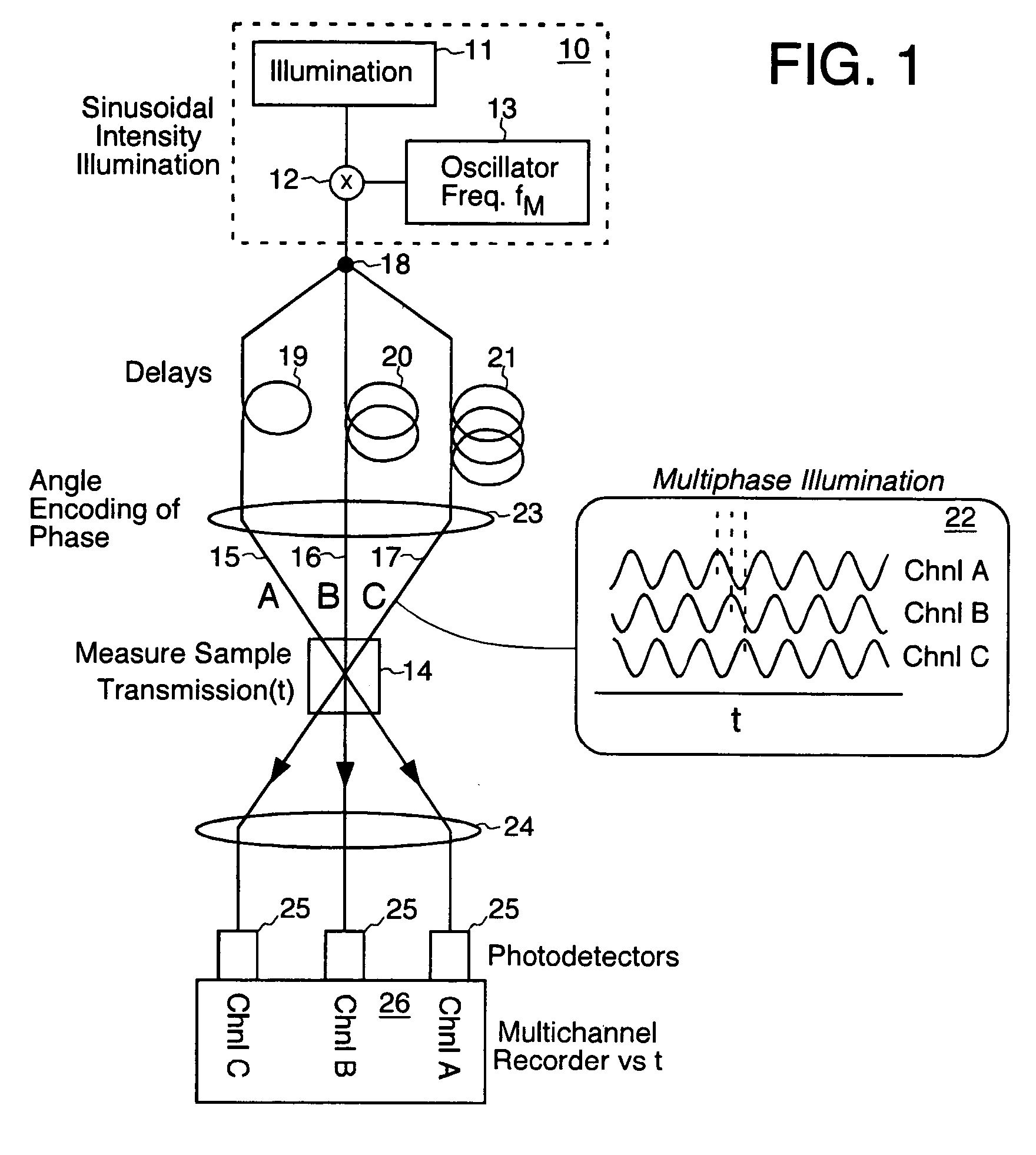
[0067] Turning now to the drawings, FIG. 1 shows an embodiment of the invention that uses multiple phase-differentiated illumination channels, e.g. 15, 16, and 17, encoded by angle to measure a sample 14 transmission (or reflectivity) versus time. A light source 10 which has a sinusoidal variation of intensity versus time at frequency fM illuminates the sample. This could be created for example from a constant illumination source 11 by modulating light at an intensity modulator 12 controlled by a local oscillator signal 13 having frequency fM. This fM is referred to as a modulating or heterodyning frequency. The intensity modulator 12 could be implemented by an acousto-optical device commonly used in the laser sciences, which uses sound waves traveling in a crystal to diffract a beam of light away from a non-diffracted output into a diffracted output. Applying an oscillating voltage at frequency fM to the acousto-optic eleme


PUM


Abstract

A method for enhancing the temporal resolving power of an optical signal recording system such as a streak camera or photodetector by sinusoidally modulating the illumination or light signal at a high frequency, approximately at the ordinary limit of the photodetector's capability. The high frequency information of the input signal is thus optically heterodyned down to lower frequencies to form beats, which are more easily resolved and detected. During data analysis the heterodyning is reversed in the beats to recover the original high frequencies. When this is added to the ordinary signal component, which is contained in the same recorded data, the composite signal can have an effective frequency response which is several times wider than the detector used without heterodyning. Hence the temporal resolving power has been effectively increased while maintaining the same record length. Multiple modulation frequencies can be employed to further increase the net frequency response of the instrument. The modulation is performed in at least three phases, recorded in distinct channels encoded by wavelength, angle, position or polarization, so that during data analysis the beat and ordinary signal components can be unambiguously separated even for wide bandwidth signals. A phase stepping algorithm is described for separating the beat component from the ordinary component in spite of unknown or irregular phase steps and modulation visibility values. This algorithm is also independently useful for analyzing interferograms or other phase-stepped interferometer related data taken with irregular or unknown phase steps, as commonly found in industrial vibration environments.

Description


Claims


Application Information

Patent Timeline
Owner LAWRENCE LIVERMORE NAT SECURITY LLC
Why Eureka
Try Eureka