Imaging apparatus including a movable media sensor

a technology of imaging apparatus and sensor, which is applied in the field of imaging apparatus, can solve the problems of sensor housing scratching of print media, defects in print quality, and sometimes showing scratches, and achieve the effect of affecting the print quality

Active Publication Date: 2006-04-06
LEXMARK INT INC
View PDF18 Cites 4 Cited by
  • Summary
  • Abstract
  • Description
  • Claims
  • Application Information

AI Technical Summary

Benefits of technology

The technical effect of this patented technology lies in its flexibility when moving an image sensor between different locations within or outside the printing process without causing damage from friction during movement. This makes it possible to use touch-based imagers like those found inside printers instead of traditional mechanical buttons. Additionally, there are fewer opportunities where these devices could get damaged by getting stuck under heavy loads caused by gravity pulling them towards their destination.

Problems solved by technology

The technical problem addressed in this patented technology relates to improving image forming devices (IJP) used for detecting different types of printed materials without damaging them due to their position relative to other components within the device's structure.

Method used


Image

  • Imaging apparatus including a movable media sensor
  • Imaging apparatus including a movable media sensor
  • Imaging apparatus including a movable media sensor

Examples


Embodiment Construction

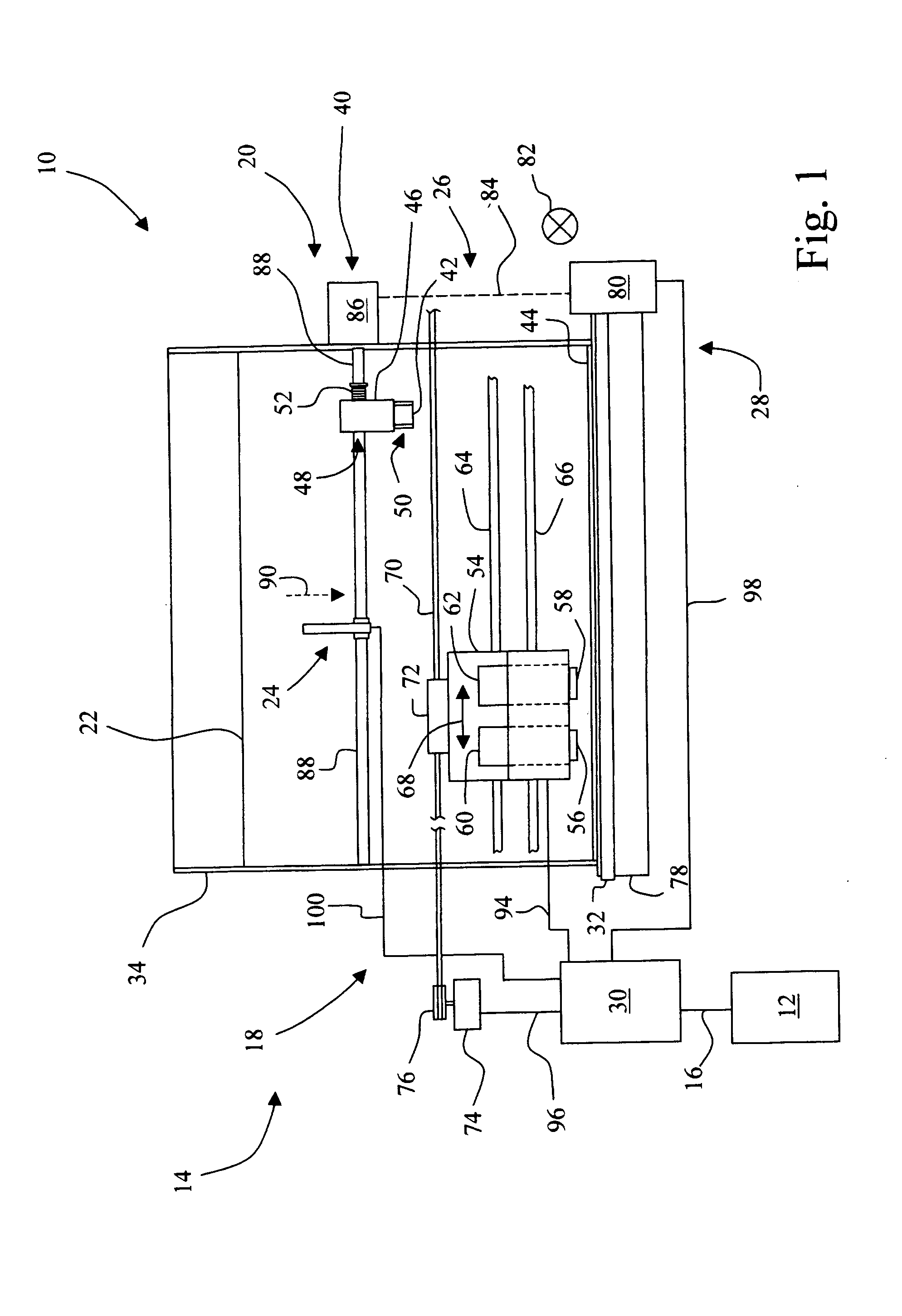
[0021] Referring now to the drawings, and particularly to FIG. 1, there is shown an imaging system 10 embodying the present invention. Imaging system 10 may include a host 12, or alternatively, imaging system 10 may be a standalone system.

[0022] Imaging system 10 includes an imaging apparatus 14, which may be in the form of an ink jet printer, as shown. Thus, for example, imaging apparatus 14 may be a conventional ink jet printer, or may form the print engine for a multi-function apparatus, such as for example, a standalone unit that has faxing and copying capability, in addition to printing.

[0023] Host 12, which may be optional, may be communicatively coupled to imaging apparatus 14 via a communications link 16. Communications link 16 may be, for example, a direct electrical connection, a wireless connection, or a network connection.

[0024] In embodiments including host 12, host 12 may be, for example, a personal computer including a display device, an input device (e.g., keyboard),


PUM


Abstract

An imaging apparatus includes a printing mechanism having a media path. A print media source is provided for supplying a sheet of print media to the printing mechanism. A drive unit is provided, with a drive shaft coupled to the drive unit. A media sensor device is mounted to the drive shaft, wherein as the drive shaft is rotated in a first direction the media sensor device is moved from a first position that is out of the media path to a second position that is in the media path for sensing the sheet of print media. As the drive shaft is rotated in a second direction opposite to the first direction the media sensor device is moved from the second position that is in the media path for sensing the sheet of print media to the first position that is out of the media path.

Description


Claims


Application Information

Patent Timeline
Owner LEXMARK INT INC
Why Eureka
Try Eureka