Inkjet printer with interposing printhead capping mechanism

a printing head and interposing technology, applied in printing and other directions, can solve the problems of inability to service the above-mentioned system, nozzles are prone to blockage,

Inactive Publication Date: 2006-06-08
MEMJET TECH LTD +1
View PDF3 Cites 16 Cited by
  • Summary
  • Abstract
  • Description
  • Claims
  • Application Information

AI Technical Summary

Benefits of technology

The technical feature described by this patented technology allows for efficient printing on different types of paper without damaging or affecting its quality during processing. This can be achieved through various mechanisms that allow for curved movement between two positions: one state before being used to make sure it fits properly into the printer's nozzles; another state after use if there are any issues with the paper passing over them.

Problems solved by technology

This patented technical problem addressed in this patents relates to improving maintenance efficiency when supplying multiple small nozzled devices called "nozzles," such as those used in ink jet printers. Current methods involve shutting down each device's entirety without performing necessary repairs before they start working properly again. Additionally, current solutions require changing all components within the printer itself, making them difficult to repair if needed over time.

Method used


Image

  • Inkjet printer with interposing printhead capping mechanism
  • Inkjet printer with interposing printhead capping mechanism
  • Inkjet printer with interposing printhead capping mechanism

Examples


Embodiment Construction

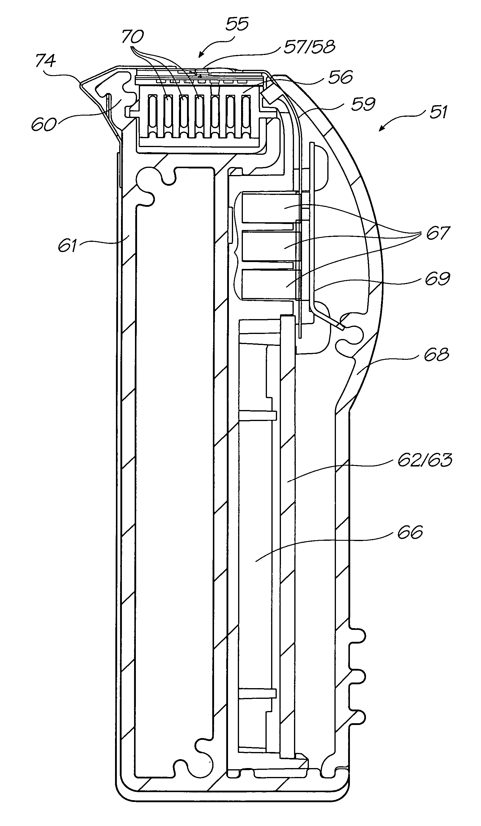
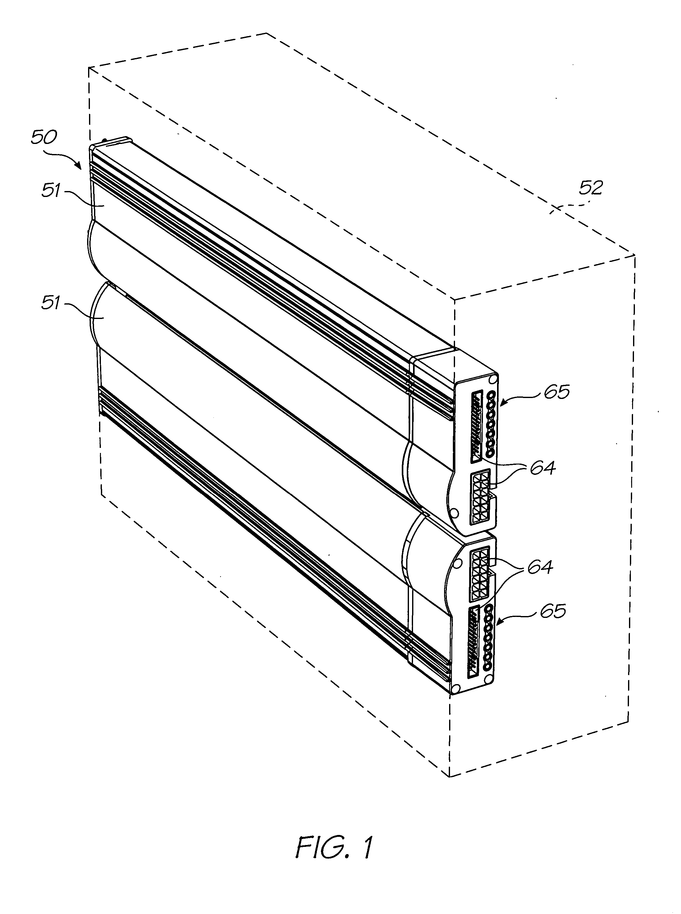
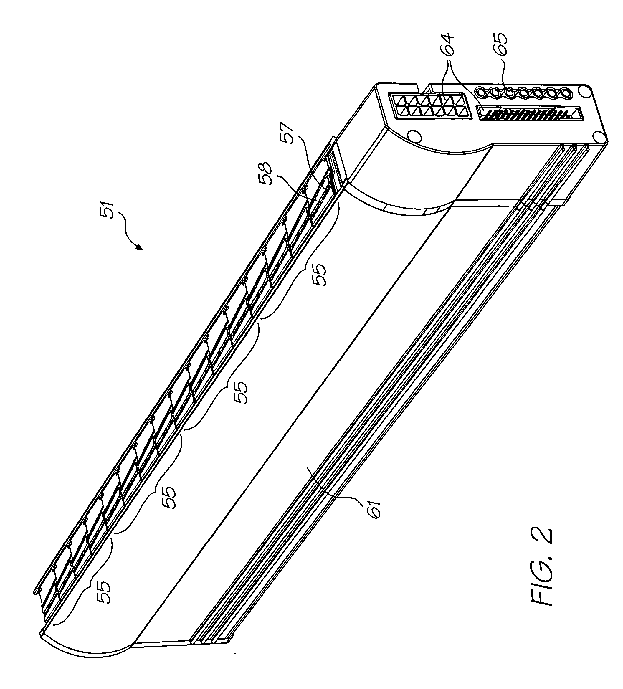
[1727] As illustrated in FIG. 1, a pagewidth printhead assembly 50 composed of two substantially identical pagewidth printheads 51 is mounted within a printer 52, although it will be understood from the following description that the printhead assembly might comprise a single printhead. The printer is shown in outline because it may be constituted by any one of a large number of printer types; including desk-top, office, commercial and wide format printers. Also, the printer may incorporate a single sheet feed system or a roll-feed system for print media (not shown), and it may be arranged for printing alpha-numeric, graphical or decorative images, the latter being relevant to the printing of textiles and wall coverings.

[1728] Each of the printheads 51 may, for example, be in the form of that which is described in the Applicant's co-pending US Patent Applications listed in the cross-references section above and all of which are incorporated herein by reference. But other types of page


PUM


Abstract

A printer is disclosed which comprises: (a) a pagewidth printhead assembly having two opposed pagewidth printheads and a plurality of nozzles located along each of the printheads for delivering ink onto print media as it is transported past the printheads, and (b) a capping mechanism having (i) a capping member located adjacent the printheads and having a length corresponding substantially to that of the printheads, (ii) a first actuating mechanism arranged to effect relative movement of the printheads from a printing first position to a spaced-apart second position and (iii) a second actuating mechanism arranged to interpose the capping member between the printheads to effect nozzle capping engagement of the two printheads when the printheads are in the second position.

Description


Claims


Application Information

Patent Timeline
Owner MEMJET TECH LTD
Why Eureka
Try Eureka