Sealing element, and drive unit containing a sealing element

a sealing element and drive unit technology, applied in the direction of engine sealing, gearing, toothed gearings, etc., can solve the problem of inability to achieve axial sealing between two axially adjacent components

Active Publication Date: 2006-08-03
ROBERT BOSCH GMBH
View PDF13 Cites 7 Cited by
  • Summary
  • Abstract
  • Description
  • Claims
  • Application Information

AI Technical Summary

Benefits of technology

The technical effect that makes it possible by having two parts - either part being made up separately from each other like o-rings or axially sealed rings (O-RING) attached onto the outer surface of the driving mechanism's housing during assembly). By doing these things securely attaching them to the motor case allows customers who want customized accessories to easily install their own equipment at home instead requiring another set of hardware such as bolts.

Problems solved by technology

This patented technical problem addressed in that patents relates to improving the performance of bearings used under high pressure environments without compromising their ability to maintain lubrication or prevent corrosion caused by external factors like water ingress during operation.

Method used


Image

  • Sealing element, and drive unit containing a sealing element
  • Sealing element, and drive unit containing a sealing element
  • Sealing element, and drive unit containing a sealing element

Examples


Embodiment Construction

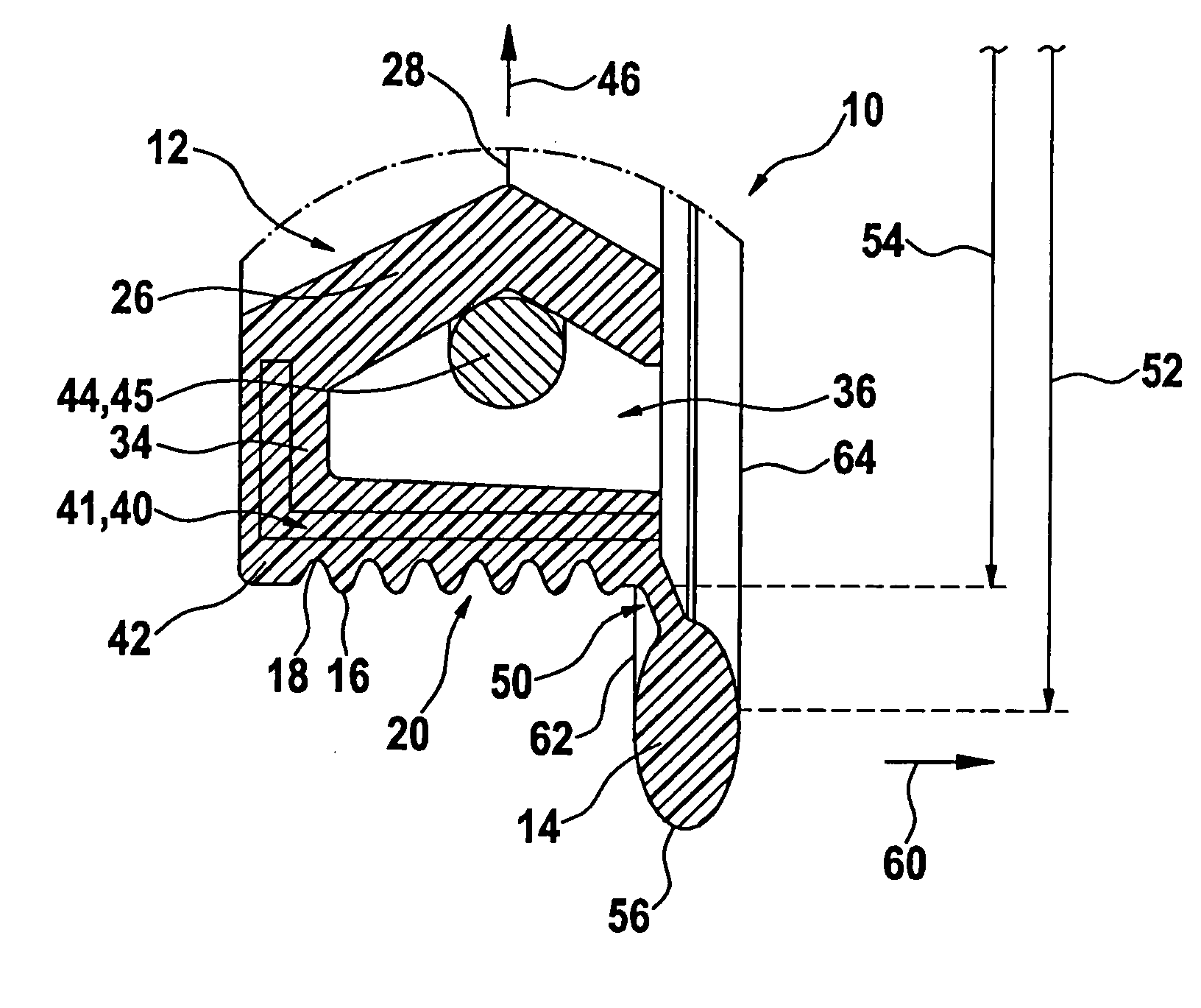
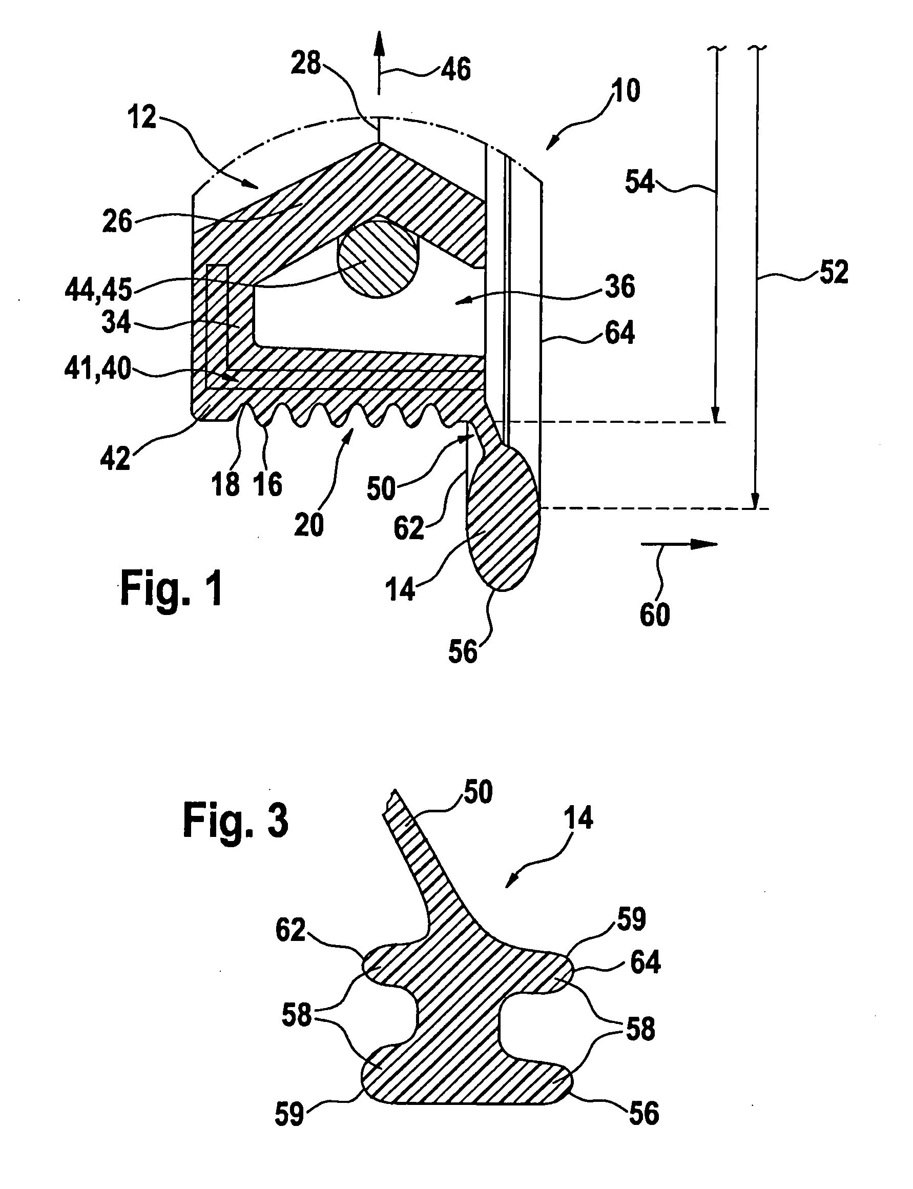
[0022] In FIG. 1, a sealing element 10 is shown, which has a radial shaft sealing ring 12 that is joined to an axial sealing ring 14. The radial shaft sealing ring 12 has a radial sealing face 16, which in the exemplary embodiment has a structuring 20 embodied as grooves 18. This structuring 20 serves to compensate for pressure peaks and for better adhesion to an outer component 22 to be radially sealed off. Diametrically opposite the outer sealing face 16, a sealing lip 26 is integrally formed onto the radial shaft sealing ring 12 and has a sealing edge 28 for radial contact with an inner component 30. The inner sealing lip 26 is joined to the outer sealing face 16 via a connecting region 34 extending in the radial direction, so that the radial shaft sealing ring 12 has a substantially U-shaped profile 36. The sealing element 10 in the exemplary embodiment is produced by means of an injection-molding process, in which a metal support ring 40, as an inlay part, is spray-coated with a s


PUM


Abstract

A sealing element for sealing off a drive unit, having a radial shaft sealing ring that has a radial sealing face for sealing off from a first component and a diametrically opposed radial sealing lip for sealing off from a further rotatable component, in which an axial sealing ring for axial sealing of a third component is integrally formed onto the radial shaft sealing ring.

Description


Claims


Application Information

Patent Timeline
Owner ROBERT BOSCH GMBH
Why Eureka
Try Eureka