Wireless motion activated light fixture base plate and kit

a technology of motion-activated light fixtures and base plates, which is applied in the direction of mechanical actuation of burglar alarms, instruments, lighting and heating apparatuses, etc., can solve the problems of high parts and labor costs

Inactive Publication Date: 2006-08-03
COLEMAN CABLE INC
View PDF9 Cites 10 Cited by
  • Summary
  • Abstract
  • Description
  • Claims
  • Application Information

AI Technical Summary

Benefits of technology

This patented technology describes how different types of devices can work together for better performance when they are used at once by connecting them wirelessly through wires without being limited by their batteries. These connections allow these devices to operate properly even if there’re no accessory device nearby like another phone on your own handset.

Problems solved by technology

This patented technical problem addressed in this patents relates to providing a way for people who want to install lights without having them pay extra money due to lack of sensitivity at nighttime when they don't use traditional cameras like those used indoors.

Method used


Image

  • Wireless motion activated light fixture base plate and kit
  • Wireless motion activated light fixture base plate and kit
  • Wireless motion activated light fixture base plate and kit

Examples


Embodiment Construction

)

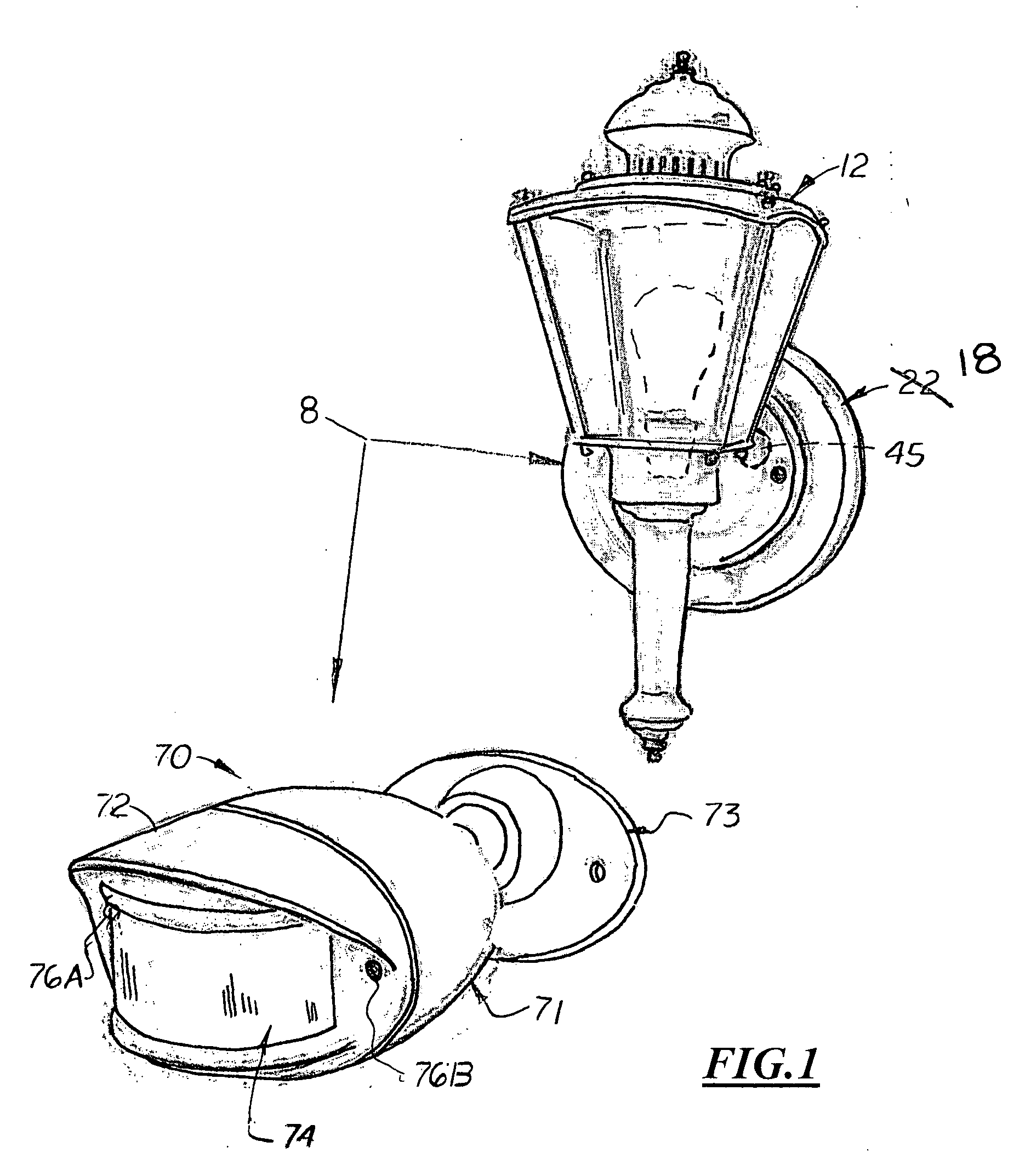
[0021] Shown in the accompanying Figs. there is shown a kit, generally referenced as 8, designed to convert a standard light fixture 12 into a motion activated light fixture 12. The electrical box cover plate 18 may be sold and distributed separately or combined in a kit 8 with a wireless motion detector 70 capable of transmitting signals to the wireless receiver 46 located in the cover plate 18.

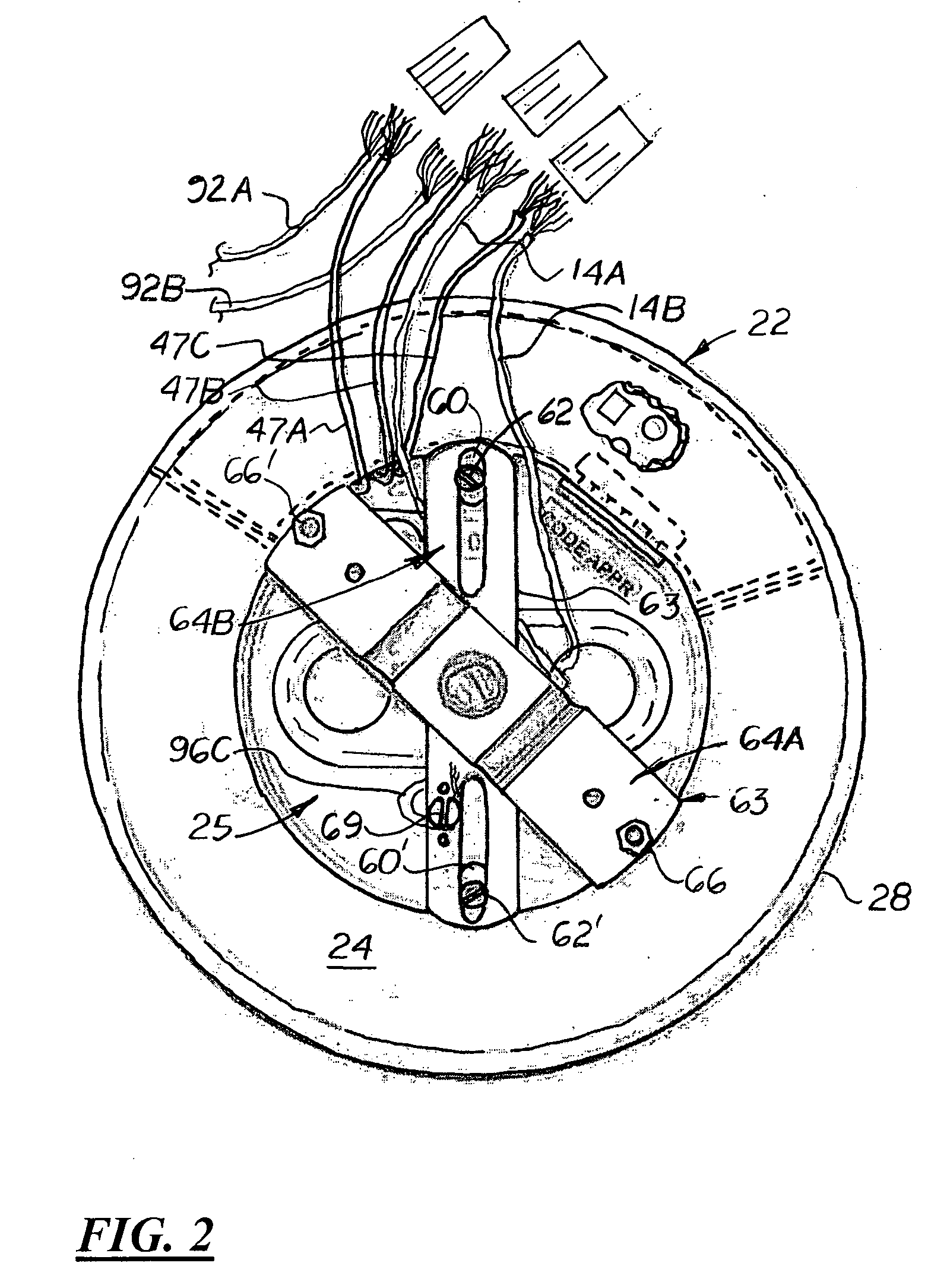
[0022] In the preferred embodiment, the cover plate 18 is a cylindrical structure with a flat front surface 20 and curved outer sidewalls 22. Formed centrally on the front surface 20 is a cylindrical recessed front cavity 25. The depth of the front cavity 25 and the width of the sidewalls 22 are substantially identical so that the cover plate 18 may be mounted flush on a flat, vertical support surface 90.

[0023] As shown in FIG. 3, formed on the back of the cover plate 18 is a ring cavity 28. The ring cavity 28 is divided into two first and second rear cavities 31, 33 by two radially aligned


PUM


Abstract

A light fixture wireless motion detector conversion kit that includes an electrical box cover plate that houses a wireless receiver unit capable of receiving a signal from a wireless motion detector. Formed on the front surface of the plate is a center cavity upon which a standard light fixture bracket is attached. During assembly, the cover plate is securely attached to a vertical support surface while the base of a light fixture is attached to the bracket. The wireless receiver unit is electrically connected between an external 120 volt AC electrical circuit and the light fixture's wires. In the preferred embodiment, the wireless receiver unit includes an optional frequently switch, a mode switch, that allows the user to select different frequencies that matches the frequency used by the motion detector.

Description


Claims


Application Information

Patent Timeline
Owner COLEMAN CABLE INC
Why Eureka
Try Eureka