Handover between mobile communication networks

a mobile communication network and call technology, applied in the direction of network data management, electrical equipment, selection arrangements, etc., can solve the problems of inability to scan broadly for available networks, the list of available cells may become too large in practical terms for user equipment, and the inability to select, etc., to facilitate handover and facilitate handover.

Inactive Publication Date: 2006-08-31
NEC CORP
View PDF38 Cites 70 Cited by
  • Summary
  • Abstract
  • Description
  • Claims
  • Application Information

AI Technical Summary

Benefits of technology

The invention allows for efficient handovers between different types of wireless systems without requiring manual intervention or reconfiguration. It achieves this through a combination of two main technologies: one uses a mobile phone's international mobile subscriber identity module (IMSI), which identifies each device on its own network, and another uses a universal integrated circuit card identifier (UICC). These technical features improve efficiency and reliability during data transfer operations.

Problems solved by technology

The technical problem addressed in this patent text relates to selecting which available networks to use at once without compromising their quality of service (QoS). Current methods require manual intervention, making it difficult to quickly switch between different networks if they don't work well together.

Method used


Image

  • Handover between mobile communication networks
  • Handover between mobile communication networks

Examples


Embodiment Construction

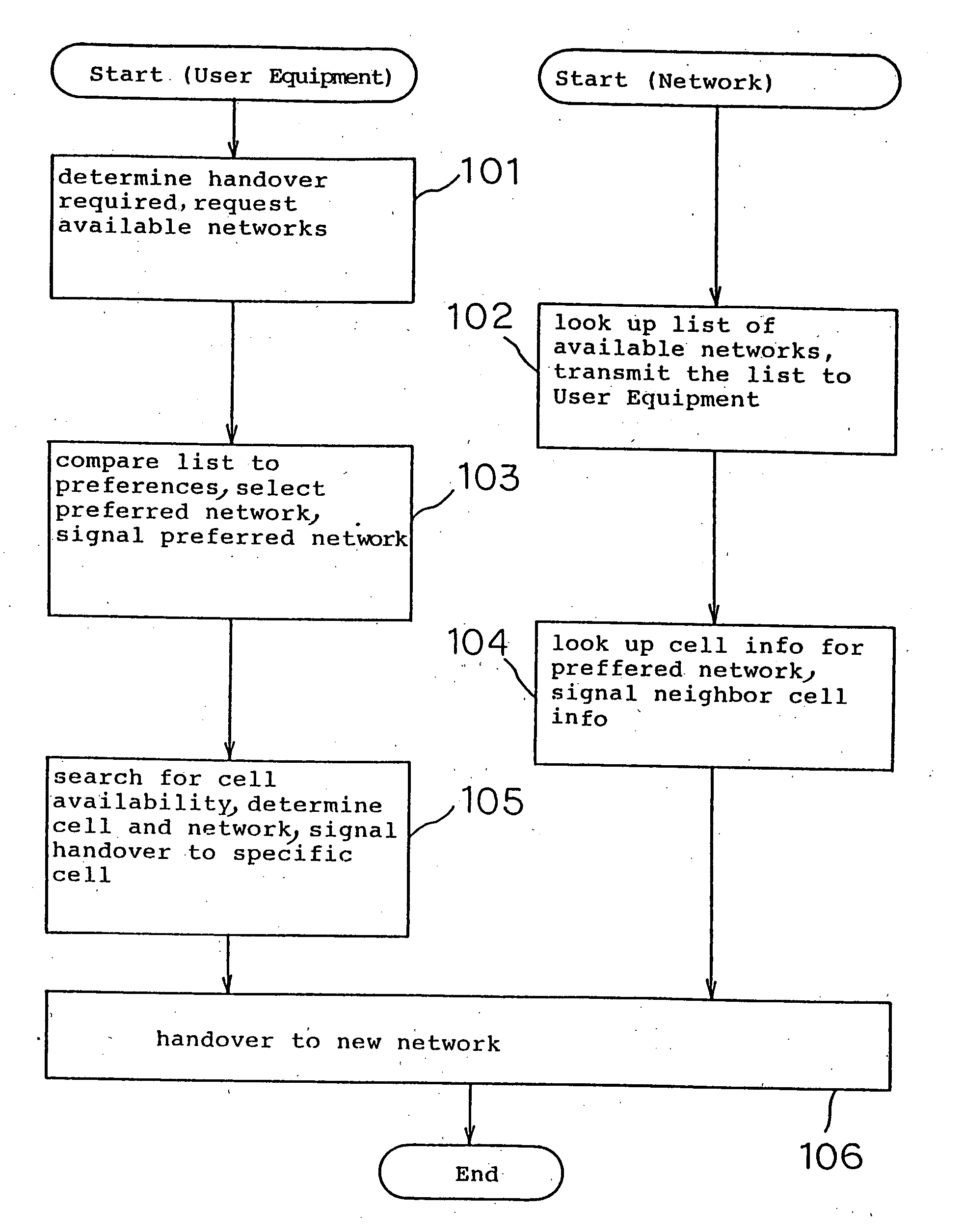
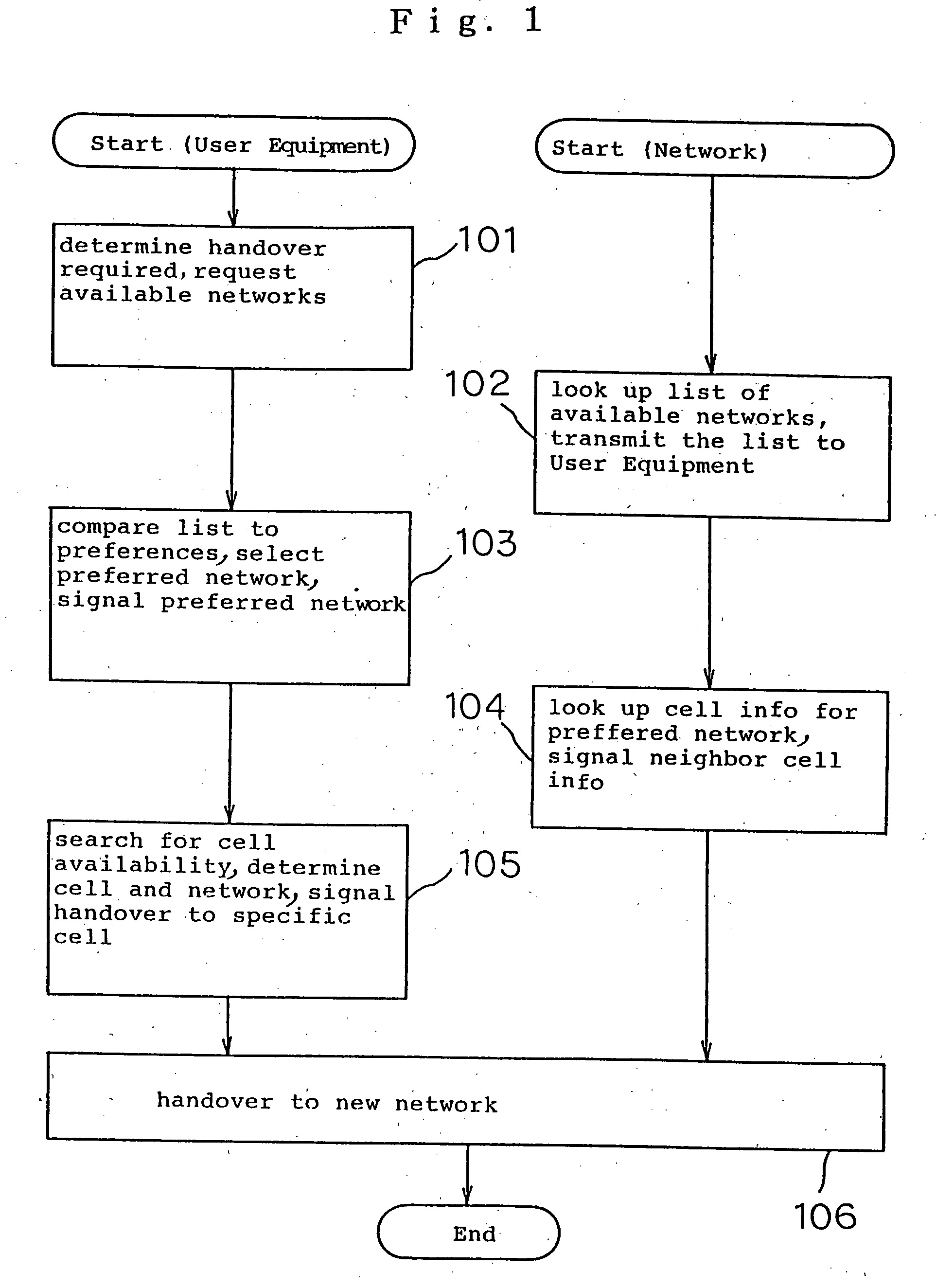
[0023] An embodiment of the invention will now be described, by way of example.

[0024] By way of explanation, we will describe in general terms, the elements of a practical implementation of a handover system embodying several of the above aspects and advantageous features. The following applies to both handover between networks of a similar type (e.g. GSM) belonging to different network providers, or between networks—of differing types (e.g. UMTS to GSM), unless otherwise stated. Indeed, in certain applications it may be possible to select between multiple networks of multiple types, for example GSM 900, GSM 1900, UMTS and local coverage networks.

[0025] Features of User Equipment

[0026] In addition to “standard” user equipment features, for communicating with the networks between which handover is to be performed (for a UMTS to GSM handover, this requires a dual mode terminal), the user equipment should ideally have the following components:—

[0027] A store for a list of network prefe


PUM


Abstract

The invention provides a method of handover from an active network to a selected one of a plurality of potential other networks. In addition to the overall solution, the solution proposed has several individual aspects. All subsidiary aspects are related to the common problem mentioned above and sharing the underlying common solution concept of implementing a system in which selective handover is possible and in which a list of available other networks provided by an active network can be handled and selection made by a terminal, so that neighbor cell information can be transmitted based on expressed terminal preferences.

Description


Claims


Application Information

Patent Timeline
Owner NEC CORP
Why Eureka
Try Eureka