Control system and method

a control system and control method technology, applied in the field of mathematical model based control systems, can solve the problems of not being able to simultaneously optimize the requirements for input parameter distribution, and modern work machines often require complex control systems to control a wide range of operations

Active Publication Date: 2006-10-12
CATERPILLAR INC
View PDF99 Cites 51 Cited by
  • Summary
  • Abstract
  • Description
  • Claims
  • Application Information

AI Technical Summary

Benefits of technology

This patent describes methods for controlling systems that use inputs and outputs in order to achieve specific goals such as optimizing performance or reducing costs. These techniques involve analyzing data records related to these inputs and outputs to identify relationships between them. Based on this analysis, the system can adjust its behavior accordingly.

Problems solved by technology
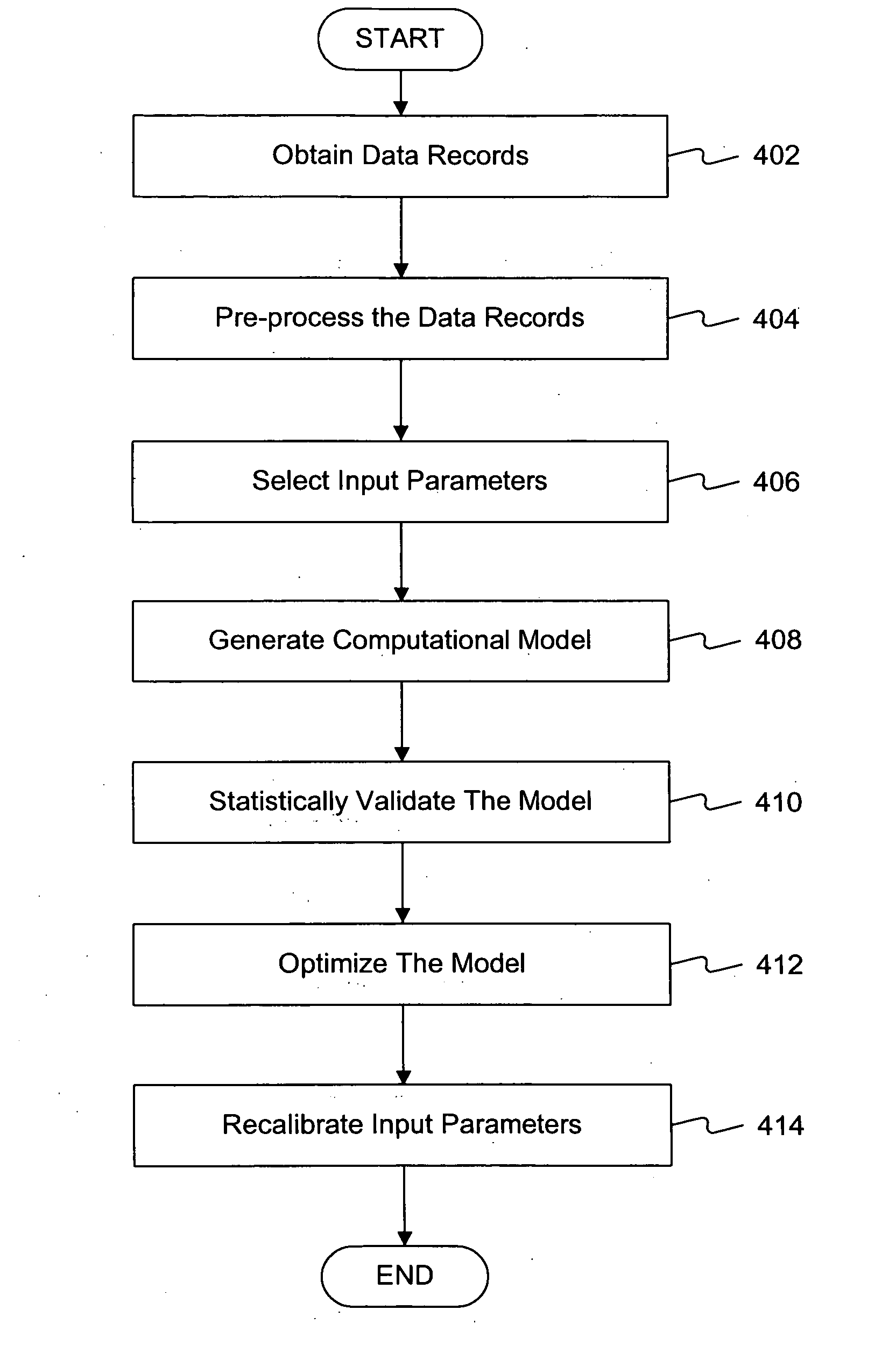
This patent describes a problem with current methods for controlling engine systems that involve complicated physical or mathematical models. These models can only adjust specific aspects of the engine's behavior but cannot optimally allocate inputs during different stages of its life cycle. Therefore, there is a technical problem addressed by this patent.

Method used


Image

  • Control system and method
  • Control system and method
  • Control system and method

Examples


Embodiment Construction

[0014] Reference will now be made in detail to exemplary embodiments, which are illustrated in the accompanying drawings. Wherever possible, the same reference numbers will be used throughout the drawings to refer to the same or like parts.

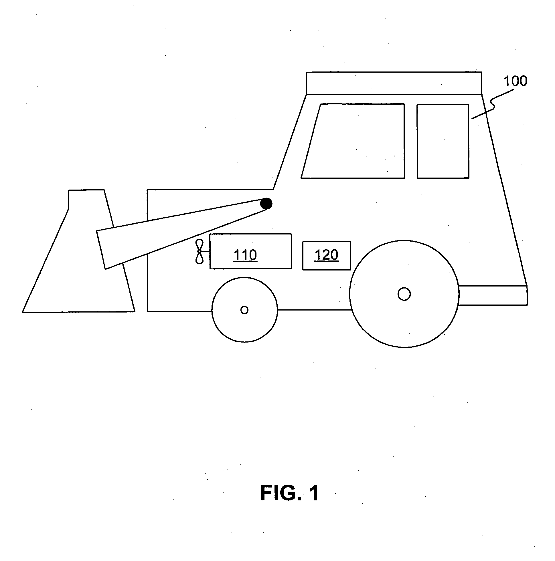
[0015]FIG. 1 illustrates an exemplary work machine 100 in which features and principles consistent with certain disclosed embodiments may be incorporated. Work machine 100 may refer to any type of fixed or mobile machine that performs some type of operation associated with a particular industry, such as mining, construction, farming, transportation, etc. and operates between or within work environments (e.g., construction site, mine site, power plants and generators, on-highway applications, etc.). Non-limiting examples of mobile machines include commercial machines, such as trucks, cranes, earth moving vehicles, mining vehicles, backhoes, material handling equipment, farming equipment, marine vessels, aircraft, and any type of movable machine that


PUM


Abstract

A method is provided for a control system. The method may include obtaining data records associated one or more input variables and one or more output parameters, and selecting one or more input parameters from the one or more input variables. The method may also include generating a computational model indicative of interrelationships between the one or more input parameters and the one or more output parameters based on the data records, and determining desired respective statistical distributions of the one or more input parameters of the computational model.

Description


Claims


Application Information

Patent Timeline
Owner CATERPILLAR INC
Why Eureka
Try Eureka