Optical system design

a technology of optical system and optical axis, applied in non-linear optics, instruments, optics, etc., can solve the problems of severely deteriorating image quality of display, and achieve the effect of improving the display quality of the lcd apparatus

Inactive Publication Date: 2006-11-16
NAT CHIAO TUNG UNIV
View PDF3 Cites 4 Cited by
  • Summary
  • Abstract
  • Description
  • Claims
  • Application Information

AI Technical Summary

Benefits of technology

This patented technology improves how well your liquid crystal displays look when viewed from different angles or at varying distances without getting annoyed due to any issues like ghost images caused by external factors such as reflection off surfaces on which it's viewers are looking for their eyesight. By adjusting the orientation of this type of lens within certain specifications, we aimed towards reducing these problems while maintaining good image performance over longer periods of time.

Problems solved by technology

The technical problem addressed in this patents relating to improving the performance of Liquid Crystalline Display Devices (LC displays) involves finding ways to improve their displaying characteristics without causing unwanted effects such as ghostings caused by external sources like ambient lights or other lamps.

Method used


Image

  • Optical system design
  • Optical system design
  • Optical system design

Examples


Embodiment Construction

[0026] To make it easier for our examiner to understand the objective of the invention, its innovative features and performance, a detailed description and technical characteristics of the present invention are described together with the drawings as follows.

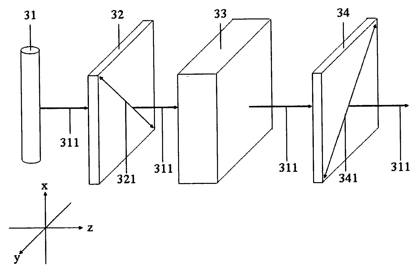
[0027] Referring to FIG. 6, it is an optical system design according to the present invention. The optical system design comprises a light generation module 31, a circular polarization module 61 and a liquid crystal light valve 33. The liquid crystal light valve 33 can be a vertical alignment liquid crystal light valve, in particularly, negative vertical alignment liquid crystal light valve. In this embodiment, the liquid crystal light valve 33 is a transparent liquid crystal light valve and then this optical system design is a transparent liquid crystal system design. The light generation module 31 which is used to generate a light beam 62 can be a light source module of a projector or a back-lighted module. The present invention


PUM


Abstract

This invention discloses an optical system design, which is used in a liquid crystal display apparatus. The optical system design at least comprises a light generation module, a circular polarization module and a liquid crystal light valve, wherein the light generation module is used to generate a light, the circular polarization module is used to modulate the polarization state of the light to a circular polarization state, and the liquid crystal light valve is used to modulate the polarization state of the light, so as to modulate the intensity of the light to show the image. The optical system design is able to solve the problem of fringing-field effects.

Description


Claims


Application Information

Patent Timeline
Owner NAT CHIAO TUNG UNIV
Why Eureka
Try Eureka