Method for manufacturing thin film transistors

Inactive Publication Date: 2006-12-21
IND TECH RES INST
View PDF7 Cites 29 Cited by
  • Summary
  • Abstract
  • Description
  • Claims
  • Application Information

AI Technical Summary

Benefits of technology

[0012] The deposition temperature of the present invention is as low as 20□C-90□C. Its low deposition temperature allows the use of flexible substrates, such as plastic substrates. It also offers the advantages of no practical limit of panel size, low fabrication cost and safe environment. Furthermore, the fabrication cost is significantly reduced if multiple panels are processed simultaneously.

Problems solved by technology

This not only requires high-energy consumption but also limits the choices of panel substrates and panel sizes.
The drawback of the organic TFTs is that their performance (e.g., carrier mobility and ratio of on-current and off-current Ion/Ioff) is much inferior to their a-Si counterparts.
In addition, the toxic materials involved in the fabrication process are one of the major concerns of their applications.
Though low-temperature solution deposition of ZnO has gradually received attention in the research community, the applications of the deposition method to TFT fabrication have not been applied yet.

Method used


Image

  • Method for manufacturing thin film transistors
  • Method for manufacturing thin film transistors
  • Method for manufacturing thin film transistors

Examples


Example

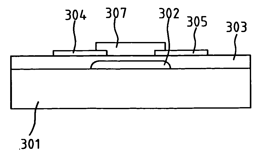
[0026] In a first embodiment of the present invention, an inverted staggered TFT is fabricated. The manufacturing method for the staggered TFT includes the formation of a gate electrode, a gate insulator, an active channel layer, a drain electrode, and a source electrode on a substrate. FIGS. 3A-3D illustrate the manufacturing flow of an inverted staggered TFT according to the present invention. FIG. 3A is a schematic cross-sectional view of the inverted staggered TFT having a gate electrode, an insulator, an active channel, a drain electrode, and a source electrode on a substrate. Referring to FIG. 3A, it comprises the following fabrication steps. (a1) depositing a first conducting layer and patterning the first conducting layer to form a gate electrode 302 on a substrate 301. (a2) depositing and patterning a high-dielectric-constant insulating layer 303 on the gate electrode 302 and part of the substrate 301, (a3) depositing a second conducting layer and patterning the second conduct

Example

[0029] In a second embodiment of the present invention, a co-planar TFT is fabricated. FIGS. 4A-4D illustrate the manufacturing flow of the co-planar TFT. The manufacturing method includes photo resist patterning, surface treatment, CBD film growth, photo resist stripping, depositing and patterning an insulator, and formation of drain electrode, source electrode, and gate electrode. FIG. 4A is a schematic cross-sectional view of the co-planar TFT after photo resist patterning and surface treatment. Referring to FIG. 4A, it includes the following fabrication steps. (a1) depositing and patterning a photo resist 402 to expose an active channel on a substrate 401. (a2) doing a surface treatment to enhance the adhesion of subsequent active channel layer onto the exposed active channel. The surface treatment can be a plasma etching or a chemical reaction method to embed nanostructure catalyst onto the exposed surface.

[0030]FIG. 4B is a schematic cross-sectional view after forming an active


PUM


Abstract

A method for manufacturing TFTs is provided. It can be applied to both inverted staggered and co-planar TFT structures. The manufacturing method for the staggered TFT includes the formation of a gate electrode, a gate insulator, an active channel layer, a drain electrode, and a source electrode on a substrate. It emphasizes the use of metal oxides or II-VI compounds semiconductors and low-temperature CBD process to form the active channel layer. In a CBD process, the active channel layers are selectively deposited on the substrates immersed in the solution through controlling solution temperature and PH value. The invention offers the advantages of low deposition temperature, selective deposition, no practical limit of panel size, and low fabrication cost. Its low deposition temperature allows the use of flexible substrates, such as plastic substrates.

Description


Claims


Application Information

Patent Timeline
Owner IND TECH RES INST
Why Eureka
Try Eureka