Recording medium and signal processing unit for recording medium drive

Inactive Publication Date: 2007-02-01
FUJITSU LTD
View PDF10 Cites 3 Cited by
  • Summary
  • Abstract
  • Description
  • Claims
  • Application Information

AI Technical Summary

Benefits of technology

[0007] It is accordingly an object of the present invention to provide a recording medium contributing to a sufficient discrimination

Problems solved by technology

A larger optical depth of the phase pits causes an increase in jitter in the discrimination of the re

Method used


Image

  • Recording medium and signal processing unit for recording medium drive
  • Recording medium and signal processing unit for recording medium drive
  • Recording medium and signal processing unit for recording medium drive

Examples


Embodiment Construction

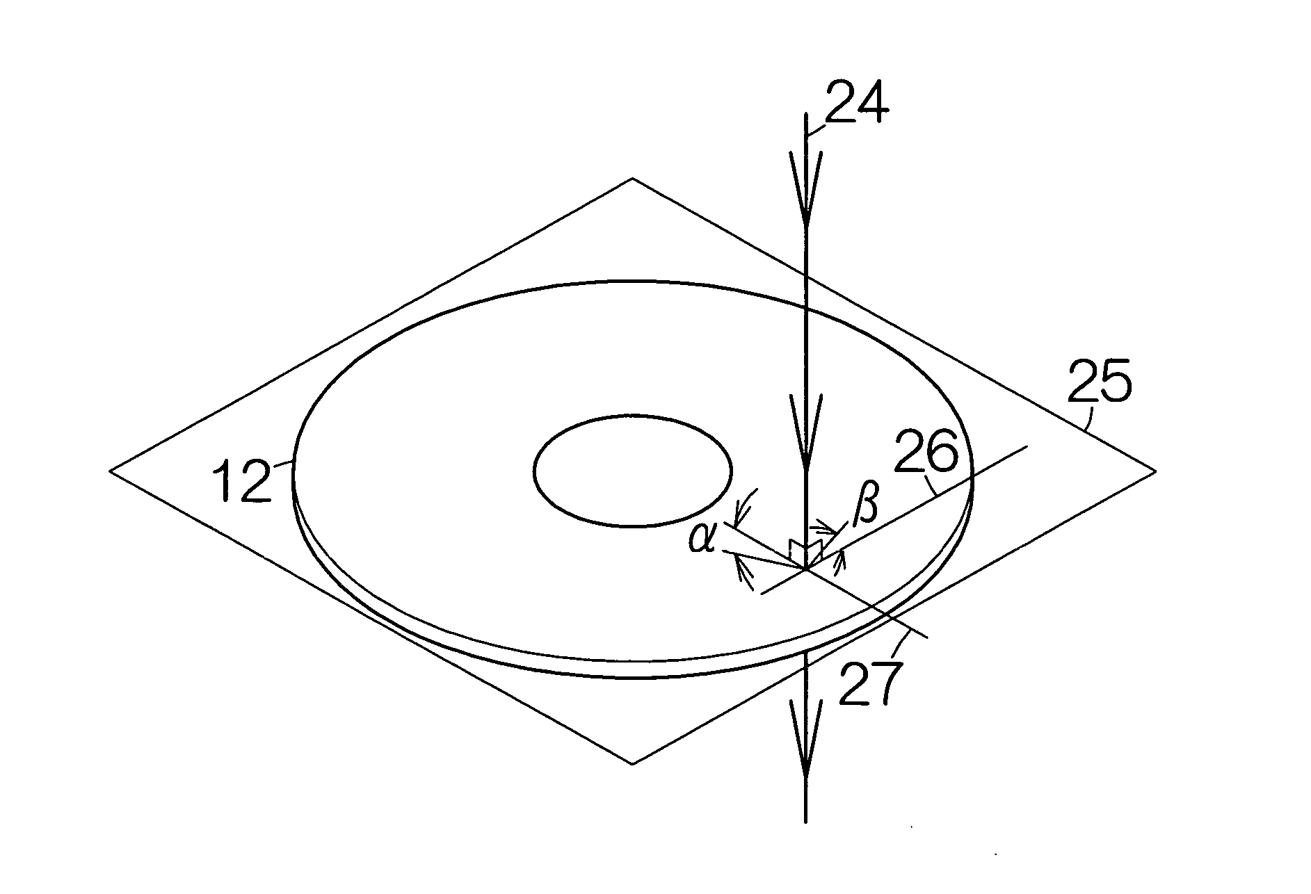
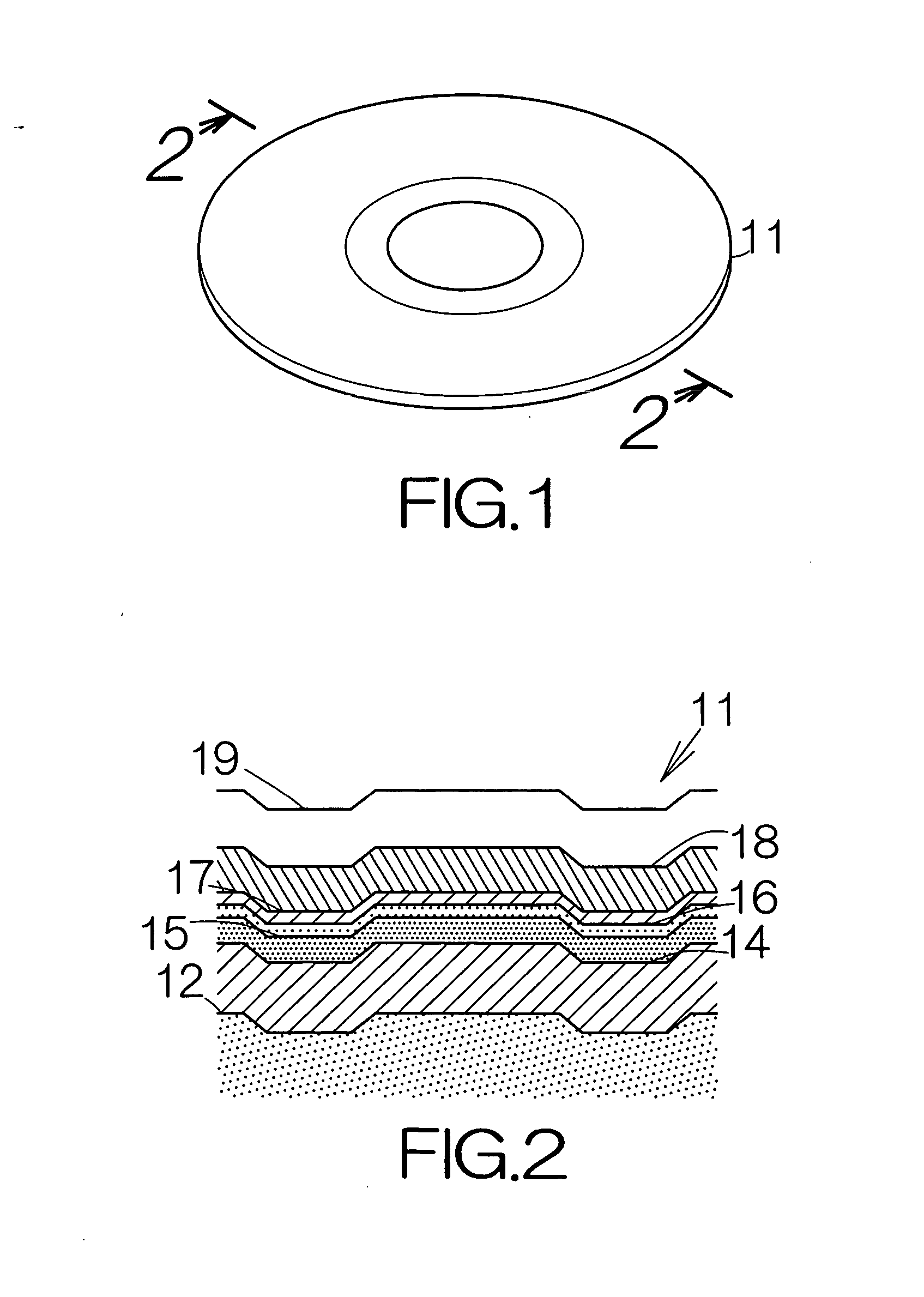
[0043]FIG. 1 illustrates a magneto-optical disk 11 as an example of a recording medium according to the present invention. The magneto-optical disk 11 is a so-called concurrent ROM-RAM magneto-optical disk. The diameter of the magneto-optical disk 11 is set at 120 mm, for example. It should be noted that such a medium might take the shape of a card or the like in place of the shape of a disk.

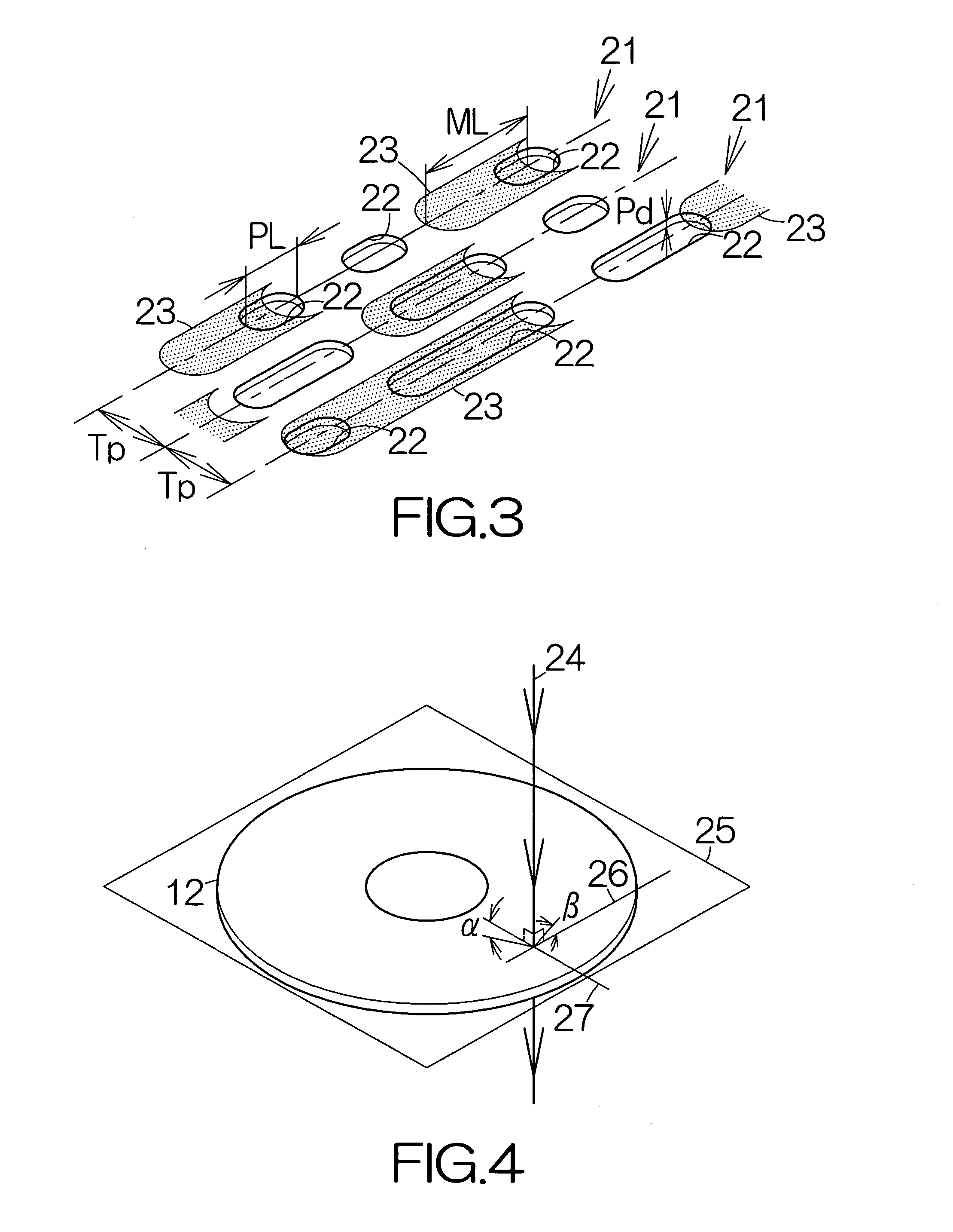
[0044]FIG. 2 schematically illustrates a sectional view of the magneto-optical disk 11. The magneto-optical disk 11 includes a substrate 12 in the shape of a disk. The substrate 12 is made of a transparent material. The transparent material may be a resin material such as polycarbonate, amorphous polyolefin, or the like. Injection molding is employed to form the substrate 12. An undercoat film 14, a magnetic recording film 15, an auxiliary magnetic film 16, an overcoat film 17, a reflection film 18 and a protection film 19 are formed on the surface of the substrate 12 in this sequence. The underco


PUM


Abstract

A magnetic film is formed over phase pit sequences in a recording medium. Recording marks are established in the magnetic film in accordance with the direction of the magnetization. A laser beam is utilized to read out information from the phase pit sequences. The laser beam is also utilized to read out information based on the recording marks. The minimum mark size of the recording marks is set larger than minimum pit length in the phase pit sequences. The recording medium allows minimization of the influence of the phase pit sequences during the readout of information based on the recording marks as compared with a recording medium having the minimum pit length equal to the minimum mark size. Information can be read out based on the recording marks with a sufficient accuracy even when the minimum pit length gets smaller in the phase pit sequences.

Description


Claims


Application Information

Patent Timeline
Owner FUJITSU LTD
Why Eureka
Try Eureka