Drive train of an all-wheel drive vehicle comprising clutches and method for controlling and regulating a drive train

Inactive Publication Date: 2007-03-15
ZF FRIEDRICHSHAFEN AG
View PDF5 Cites 4 Cited by
  • Summary
  • Abstract
  • Description
  • Claims
  • Application Information

AI Technical Summary

Benefits of technology

[0020] Furthermore, according to the invention for controlling and adjusting the power train, exists the possibility of operating one of the three clutches in a slip free condition. The other two clutches can be operated with one of the needed power output distributions and low differential rotational spe

Problems solved by technology

If the traction reserves must be used completely in case of high slippage, in theory it is only possible to brake or block the variable torque distribution between the front and rear axles of an automobile with a longitudinal

Method used


Image

  • Drive train of an all-wheel drive vehicle comprising clutches and method for controlling and regulating a drive train
  • Drive train of an all-wheel drive vehicle comprising clutches and method for controlling and regulating a drive train
  • Drive train of an all-wheel drive vehicle comprising clutches and method for controlling and regulating a drive train

Examples


Embodiment Construction

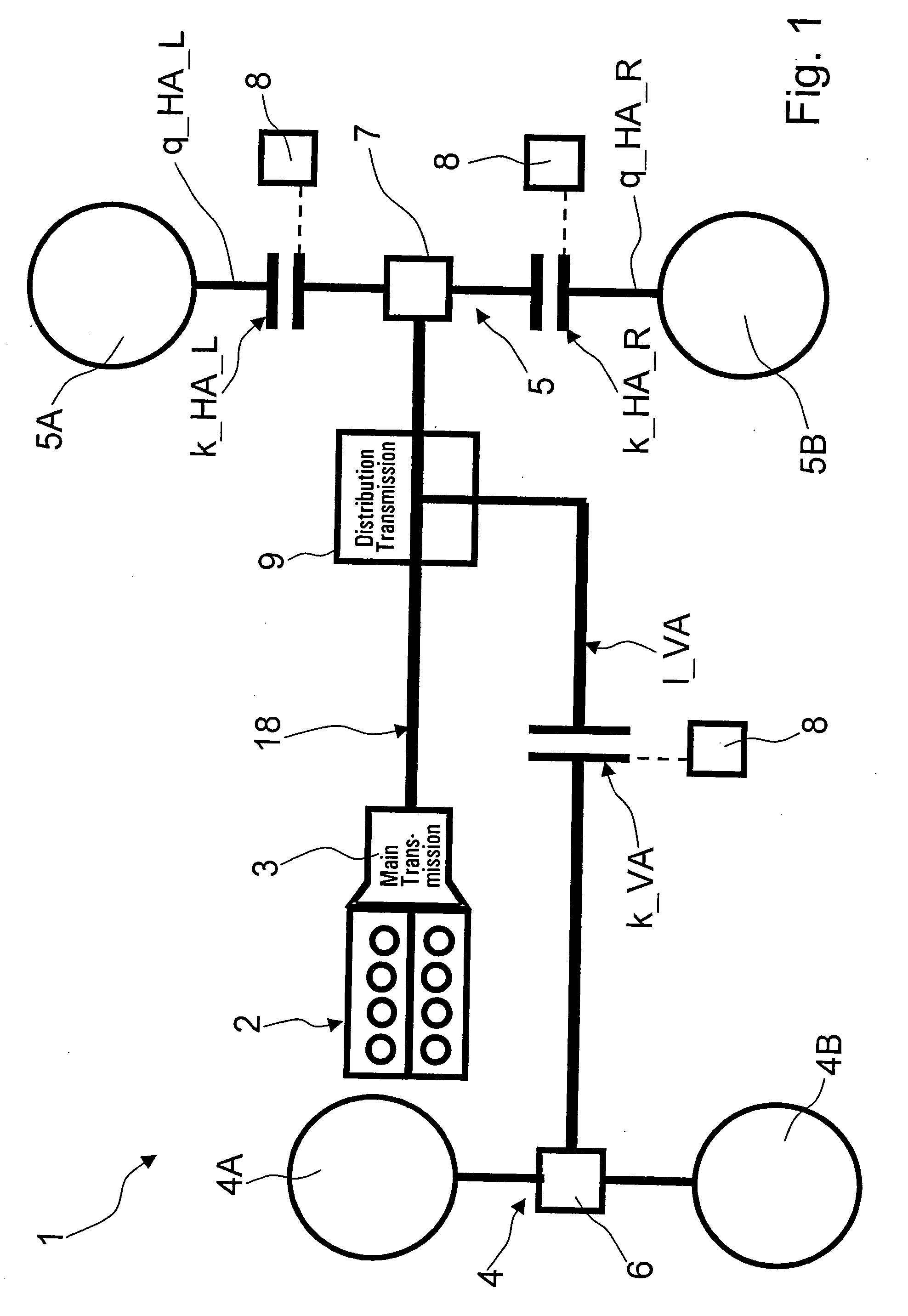
[0028]FIG. 1 shows a schematic representation of a power train 1 of an all-wheel drive vehicle. Power train 1 comprises a driving unit 2 and a main transmission 3, each of which in practice is a known transmission. The driving unit 2 is represented in the application example of FIG. 1 as a braking force machine and can be built from an electric motor for a beneficial further training.

[0029] Between the main transmission 3, which is intended for showing different conversion ratios, and a first driven vehicle axle 4, which in a known way can be connected with at least one driven wheel 4A, 4B, is a first clutch k_VA arranged in a longitudinal power train. The first clutch k_VA is between the main transmission 3 and a mechanism 6 which balances through differential rotational speeds and is placed between the driven wheels 4A and 4B, the first vehicle axle 4, whereby the mechanism 6 is used as a known transverse distributing transmission.

[0030] Beyond this, a second clutch k_HA_L as well


PUM


Abstract

A power train (1) of an all-wheel drive vehicle with at least two driven vehicle axles (4, 5), with a main transmission (3) placed between a main engine (2) and the vehicle axles (4, 5), capable of displaying different conversion ratios, which has three control and adjustment frictional clutches (k_VA, k_HA_L and k_HA_R). The first clutch (k_VA) is placed between the main transmission (3) and the first vehicle axle (4) and the second clutch (k_HA_L) and the third clutches (k_HA_R) are respectively located between an axle transmission (7) and two driven wheels (5A, 5B) of the second vehicle axle (5). The respective transfer capabilities of the clutches (k_VA, k_HA_L, k_HA_R) can be adjusted with an actuator (8), and the driving torque between the driven vehicle axles (4, 5) can be distributed depending on the adjusted transfer capabilities of the clutches (k_VA, k_HA_L, k_HA_R).

Description


Claims


Application Information

Patent Timeline
Owner ZF FRIEDRICHSHAFEN AG
Why Eureka
Try Eureka