Connection between a lateral and main pipe and method for making same

Active Publication Date: 2007-09-13
SHOOK WILLIAM E +1
View PDF19 Cites 12 Cited by
  • Summary
  • Abstract
  • Description
  • Claims
  • Application Information

AI Technical Summary

Benefits of technology

[0026] According to another feature of the present invention the entire process is accomplished

Problems solved by technology

The connection of lateral pipes to buried main pipes is a problem encountered in many new areas where new homes are being built and lateral pipes must be connected to the buried main pipe.
Another disadvantage of present methods is the accurate location of the depth of the main line pipe and the slope of the main line pipe relative to the ground surface.
Another disadvantage of present prior art methods is the lack of a cutting tool which cuts a hole in the main pipe, fits within the main line pipe, and

Method used


Image

  • Connection between a lateral and main pipe and method for making same
  • Connection between a lateral and main pipe and method for making same
  • Connection between a lateral and main pipe and method for making same

Examples


Embodiment Construction

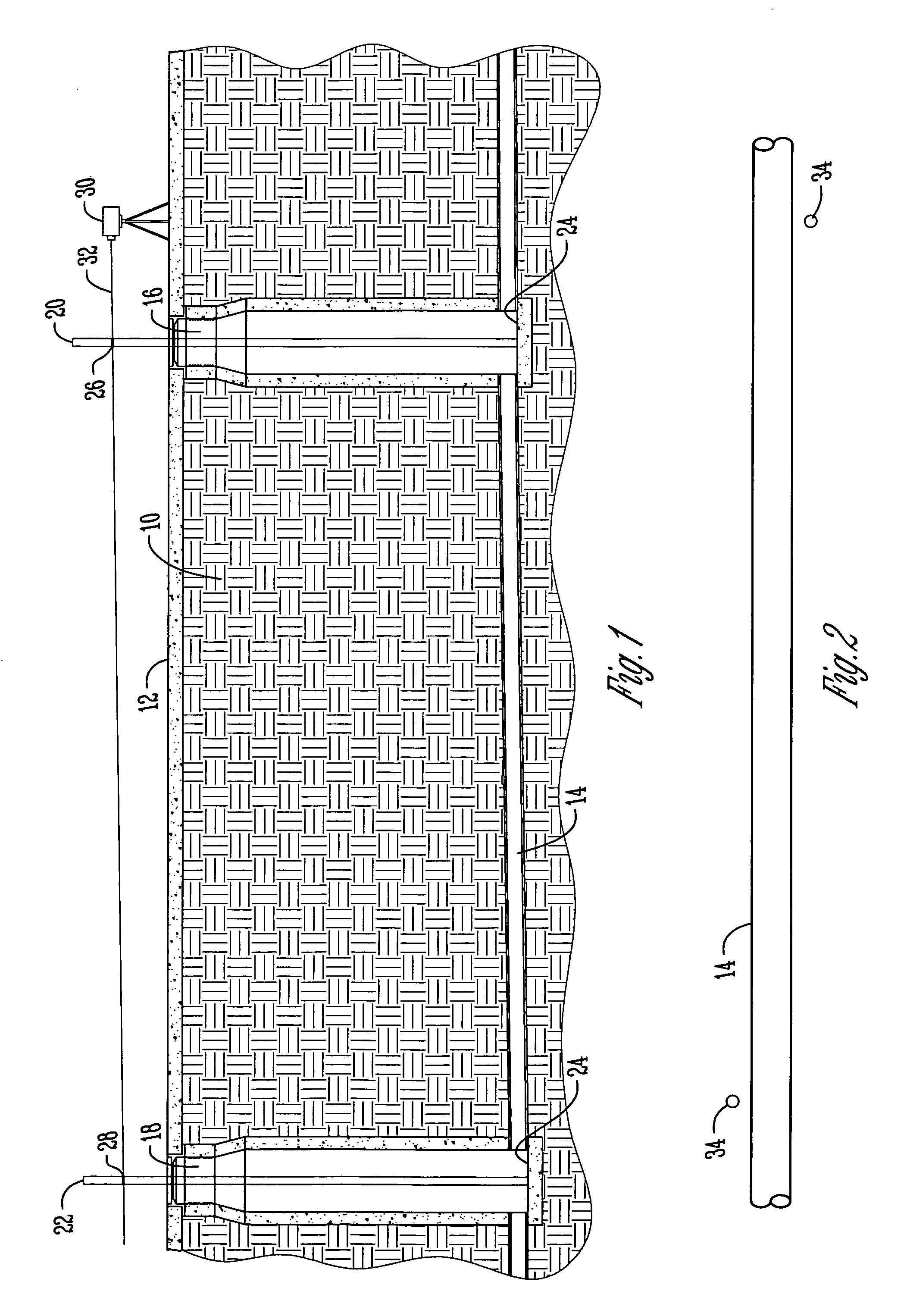
[0037] Referring to the drawings, the numeral 10 generally designates the ground in which a main sewer pipe 14 is buried. The ground surface is represented by the numeral 12. A first manhole 16 is provided in the ground in communication with the main sewer pipe 14 and a second manhole 18 is also provided in the ground 10 providing communication to a second place in the sewer pipe 14.

[0038] A first stake 20 and a second stake 22 are inserted into the first and second manholes 16, 18 respectively, and engage the bottom wall 24 of the manholes 16, 18. Each of the stakes is marked with a first stake mark 26 and a second stake mark 28 equidistant above the lower ends of the stakes 20, 22 so that the first and second stake marks provide a reference point for the slope of the main sewer pipe 14 between the two manholes 16, 18. A laser emitter 30 emits a laser beam 32 which is lined up with the marking 26, 28 on the stakes 20, 22. This shows the slope of the main sewer line 14 relative to the


PUM

PropertyMeasurementUnit
Forceaaaaaaaaaa
Pressureaaaaaaaaaa
Adhesivityaaaaaaaaaa

Abstract

Apparatus and method for connecting a lateral pipe to a main pipe are provided by a tool having a first end within the main pipe and a second end outside the lateral pipe so as to apply pressure to the below-ground connection of the main and lateral pipes from an above-ground location. The entire operation may be done without a person having to enter into an access opening in the ground to connect the lateral pipe to the main pipe. A laser is used to determine the depth of the access hole relative to the surface of the ground and the main sewer pipe.

Description


Claims


Application Information

Patent Timeline
Owner SHOOK WILLIAM E
Why Eureka
Try Eureka