System and apparatus for enclosing equipment

Inactive Publication Date: 2007-10-25
GENERAL ELECTRIC CO
View PDF8 Cites 1 Cited by
  • Summary
  • Abstract
  • Description
  • Claims
  • Application Information

AI Technical Summary

Benefits of technology

[0003] An embodiment of the invention includes an enclosure having a top and at least one side to surround equipment. A first set of ventilation ports is disposed toward the bottom of the enclosure, a second set of ventilation ports is disposed toward the top of the enclosure, and a baffle is disposed proximate the top at the interior of the enc

Problems solved by technology

Power generating equipment, such as gas turbines for example, may create significant amounts of acoustic energy (noise) during operation.
In addition to acoustic energy, many types of power generating equipm

Method used


Image

  • System and apparatus for enclosing equipment
  • System and apparatus for enclosing equipment
  • System and apparatus for enclosing equipment

Examples


Embodiment Construction

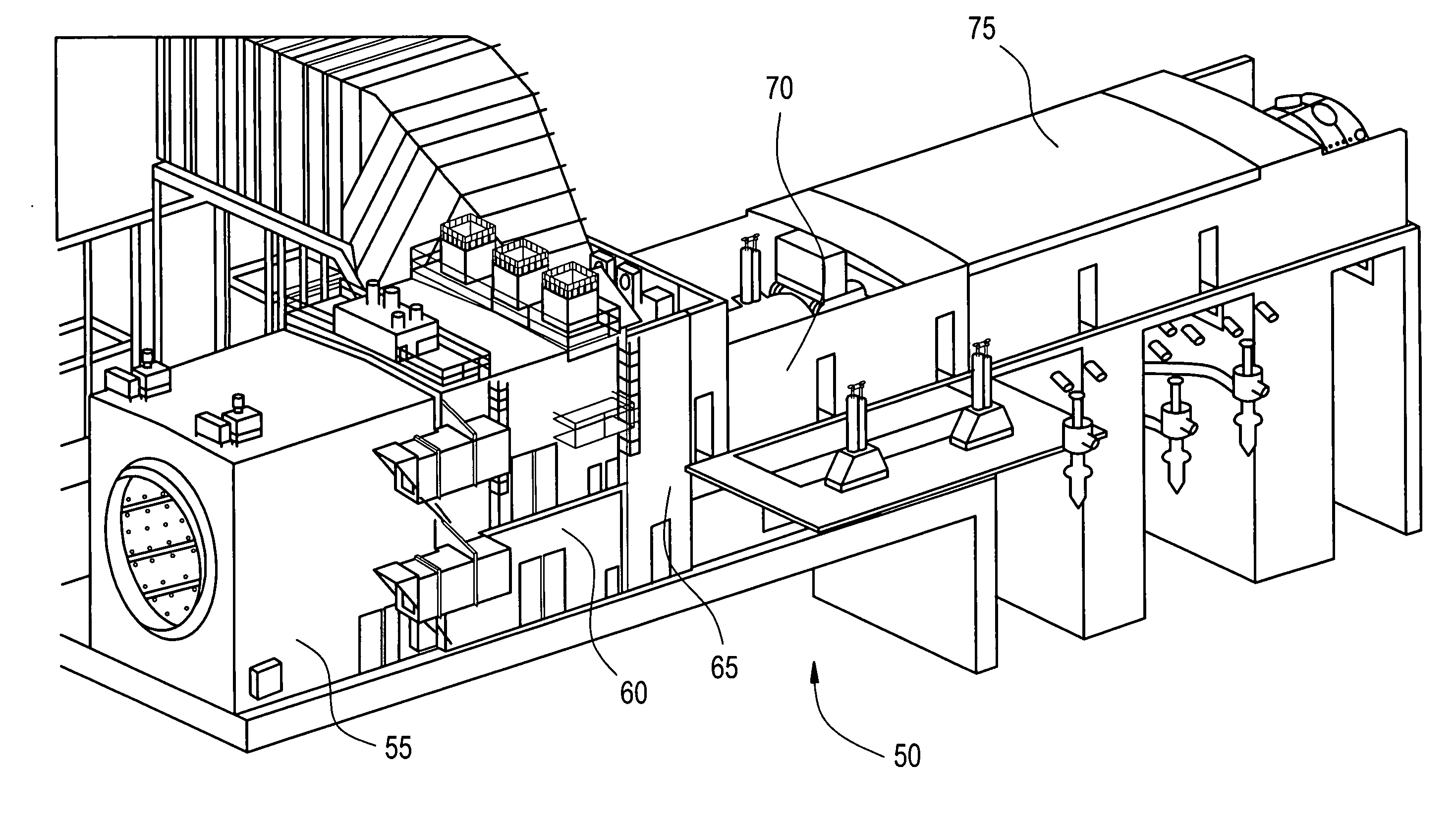
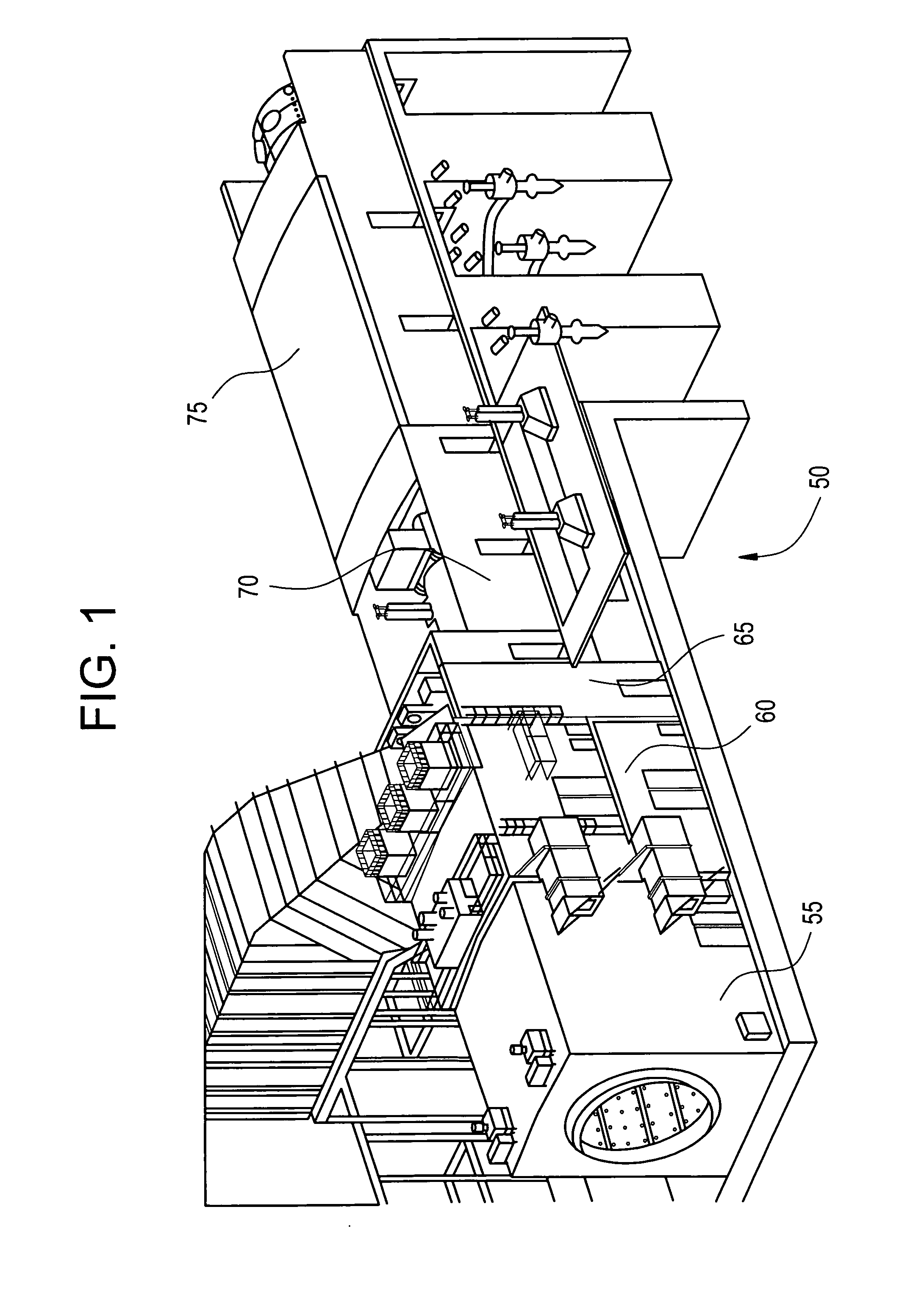
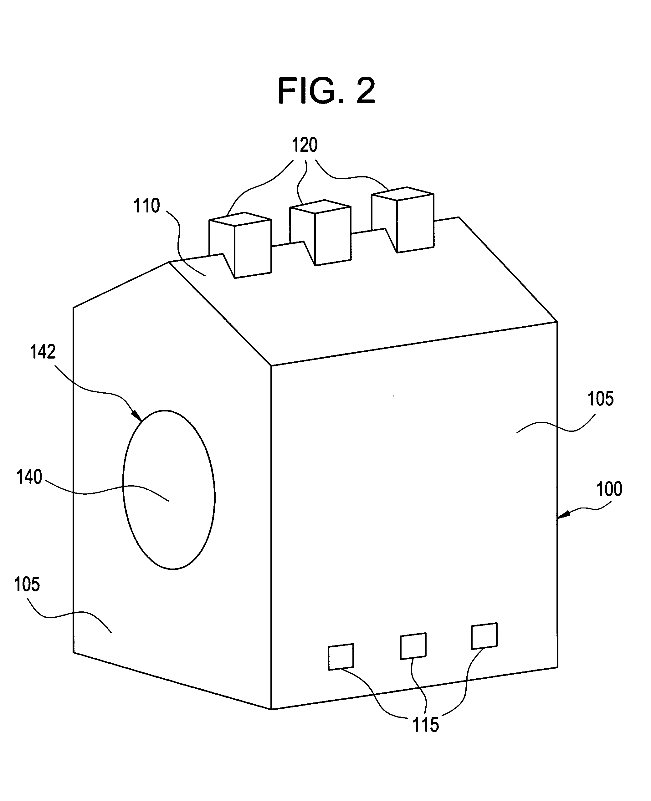
[0012] An embodiment of the invention provides a naturally ventilated power plant equipment enclosure, employing natural convection as opposed to forced convection. The enclosure is designed to limit the transmission of acoustic energy generated by the equipment, while maintaining appropriate thermal conditions for operation of the equipment. In an embodiment, the enclosure includes ventilation inlets near the enclosure bottom and ventilation outlets near the enclosure top. The inlets may be located on or near the floor or at or near the bottom of the enclosure sidewalls. The outlets may be positioned on the enclosure roof or near the top of the enclosure sidewalls. In an embodiment, outlets may be located on the top of a pitched roof to drive maximum buoyancy flow through the enclosure. If outlets are not disposed on the enclosure top, due to an obstruction for example, or for reasons relating to the desire to use the enclosure top as a storage area, for example, ventilation outlets m


PUM


Abstract

An enclosure having a top and at least one side to surround equipment is disclosed. The enclosure includes a first set of ventilation ports disposed toward the bottom of the enclosure, a second set of ventilation ports disposed toward the top of the enclosure, and a baffle disposed proximate the top at the interior of the enclosure. The top of the opening of the first set of ventilation ports is disposed to be lower than the bottom of the equipment, the bottom of the opening of the second set of ventilation ports is disposed to be higher than the top of the equipment, and the baffle is configured to direct a cooling medium toward the second set of ventilation ports.

Description


Claims


Application Information

Patent Timeline
Owner GENERAL ELECTRIC CO
Why Eureka
Try Eureka