Prosthetic sensing systems and methods

Active Publication Date: 2007-11-01
COLLEGE PARK IND INC
View PDF6 Cites 51 Cited by
  • Summary
  • Abstract
  • Description
  • Claims
  • Application Information

AI Technical Summary

Benefits of technology

[0011] To enhance versatility, the system may include a data collection module for receiving the signal from the electronic circuitry. The module may be remotely located and may communicate with the electronic circuitry through a wired or wireless connection. In addition to the affected limb system, the module may rec

Problems solved by technology

Such systems are often difficult to use, and can interfere with a normal range of motion by the user; furthermore, such systems generally provide relatively limited data.
Various onboard systems have been implemented; however, such systems generally requ

Method used


Image

  • Prosthetic sensing systems and methods
  • Prosthetic sensing systems and methods
  • Prosthetic sensing systems and methods

Examples


Embodiment Construction

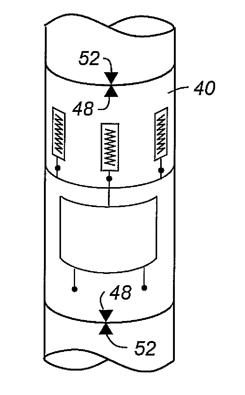
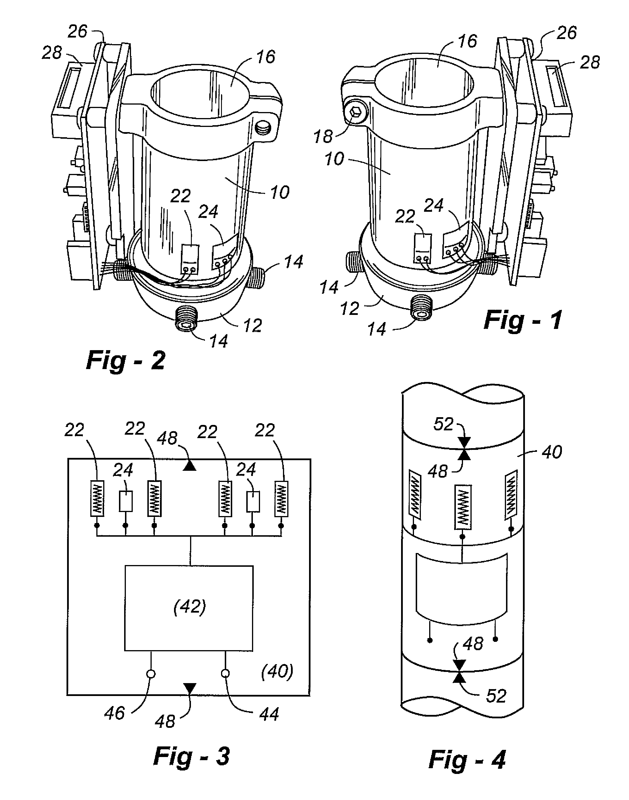
[0025] This invention relates to systems and methods for sensing forces, moments, temperature, inclination, acceleration and other parameters associated with prosthetic limbs. The preferred embodiments are capable of measuring forces relative to three designated axes, and moments about the same designated axes, for a total of six possible degrees of freedom associated with the object in three-dimensional space. The invention is applicable to legs and arms, with amputation or deficiency occurring at any point facilitating a workable coupling. In all cases a goal is to provide a sensing system that attaches to a prosthetic limb with no, or relatively minor, modification thereto.

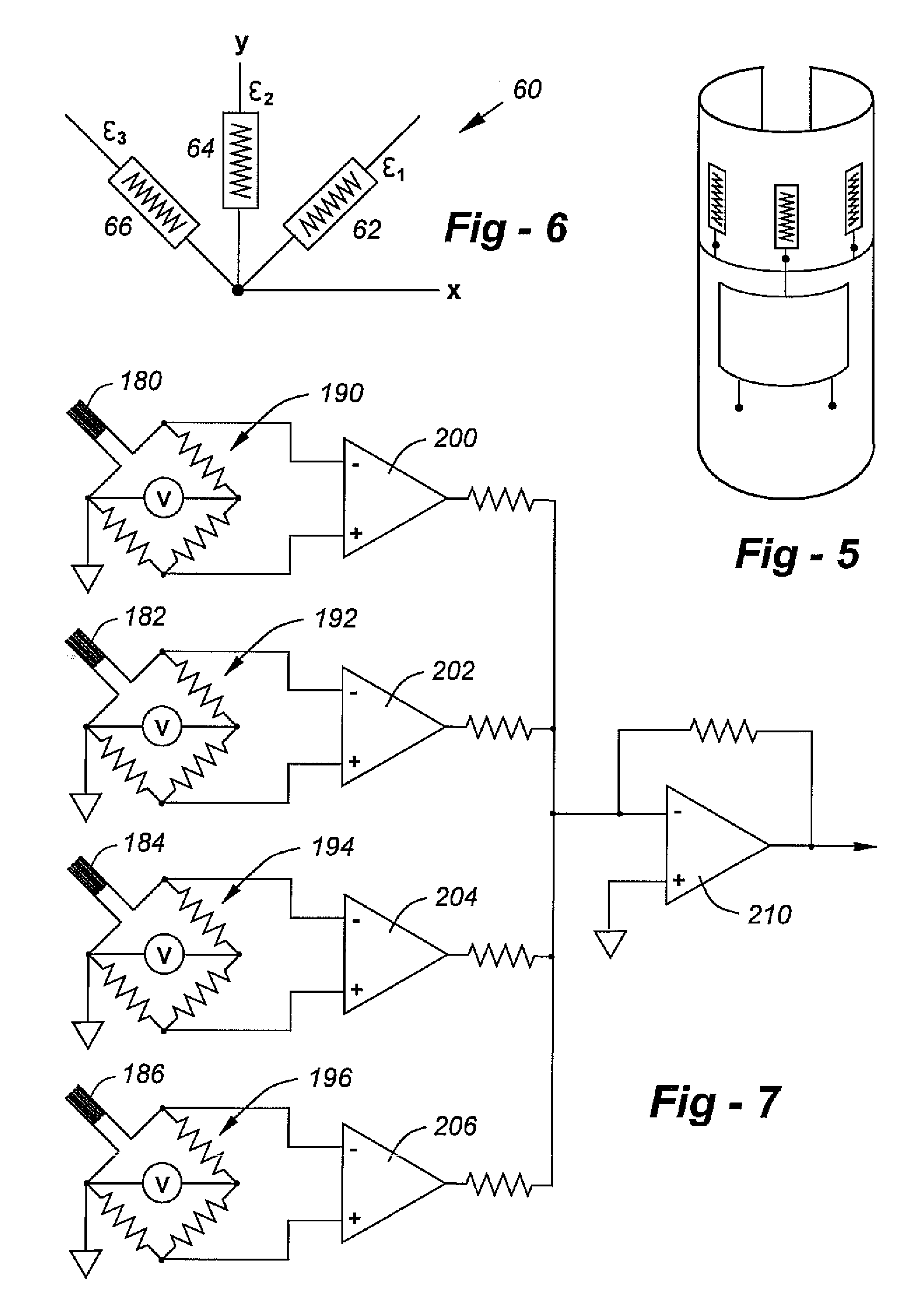
[0026] One disclosed embodiment includes a support member to which a plurality of strain gauge sensors are affixed in a preselected pattern. Each strain gauge is operative to provide a change in one of its detectable characteristics, typically electrical resistance, in response to a strain imposed on the member.


PUM


Abstract

Systems and methods are disclosed for sensing forces, moments, temperature, inclination, acceleration and other parameters associated with prosthetic limbs. The system is capable of measuring forces in three designated axes, and moments about the same designated axes, for a total of six possible degrees of freedom. The system can be readily fitted onto a conventional prosthetic limb with no, or relatively minor, modification thereto. A plurality of sensor arrays are disposed on a support member, each array including a plurality of strain gauge sensors, each sensor outputting an electrical signal responsive to loading imposed on the support member through the prosthetic limb. Electronic circuitry in communication with the gauges is operative to receive the electrical signals from the strain gauges and provide a signal useful in the form, fit or function of the prosthetic limb. The strain gauges are configured to generate positive and negative (signed) voltages to determine moments, shear forces and off-center loading. The inclinometers may be used to simulate a goiniometer. An unaffected limb electronics package and data collection module are disclosed to achieve an intelligent prosthetic endo component system.

Description


Claims


Application Information

Patent Timeline
Owner COLLEGE PARK IND INC
Why Eureka
Try Eureka