Pneumatic tire with tread siping

Inactive Publication Date: 2007-11-29
BOVAIRD LORIE JEAN +2
View PDF5 Cites 26 Cited by
  • Summary
  • Abstract
  • Description
  • Claims
  • Application Information

AI Technical Summary

Benefits of technology

[0020]“Sipes” refer to small grooves molded into tread elements of a tire that subdivide the tread elements and improve traction characteristics. Sipes have a width in the range of about 0.1% to about 1% of the tread

Problems solved by technology

The easy relative longitudinal sliding between the opposed faces of the sipe weakens the resistance of the tread elements to flexing in the contact area between tread and road and ther

Method used


Image

  • Pneumatic tire with tread siping
  • Pneumatic tire with tread siping
  • Pneumatic tire with tread siping

Examples


Embodiment Construction

[0027]The following language is of the best presently contemplated mode or modes of carrying out the invention. This description is made for the purpose of illustrating the general principles of the invention and should not be taken in a limiting sense. The scope of the invention is best determined by reference to the appended claims.

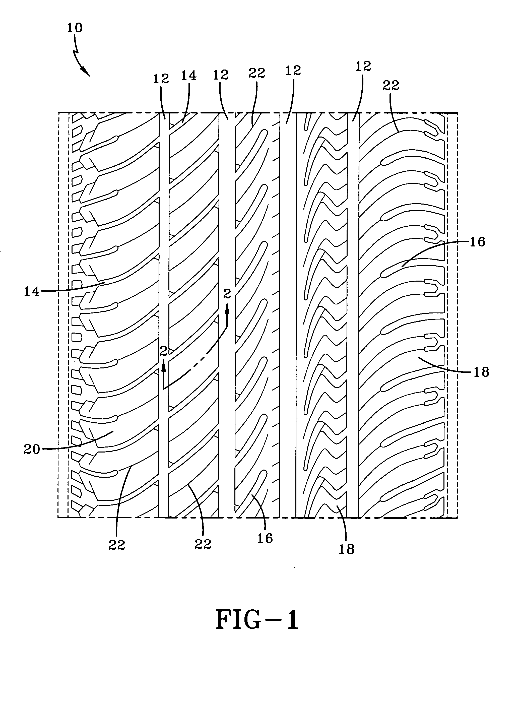
[0028]FIG. 1 is an exemplary tread 10 for a pneumatic tire. The tire employing the illustrated tread may be of a radial or bias construction; the more typical being a radial construction. The tire tread 10 has a plurality of circumferential grooves 12 and a plurality of lateral grooves 14, 16. These grooves 12, 14, 16, in different combinations from a plurality of tread elements 18, 20. Some of the lateral grooves 14 extend between the circumferential grooves 12 and some terminate within the tread element 20, creating a blind groove 16. For the illustrated tread, within each tread element 18, 20, the tread element being either a block, such as tread elemen


PUM


Abstract

A tire having a tread has at least one tread element with a multi-dimensional sipe formed in the tread element. The sipe has a width W, a depth Ds, and an effective length Le. The sipe has a first radially outermost portion with a constant effective length Le, a second transitional portion with a gradually increasing effective length Le, and a third radially innermost portion having a constant effective length Le greater than the effective length of the first portion.

Description


Claims


Application Information

Patent Timeline
Owner BOVAIRD LORIE JEAN
Why Eureka
Try Eureka