Spacecraft deorbiting electrodynamic tether

An off-orbit electricity and spacecraft technology, applied in the field of spacecraft off-orbit, can solve the problems of inability to take into account the authenticity and the convenience of analysis and calculation, the inaccuracy of the spacecraft kinematic analysis, and the unstable space state of the electrodynamic tether. , to achieve the effect of convenient theoretical analysis and model operation, convenient modeling, and simple state control

Active Publication Date: 2019-01-25
BEIHANG UNIV
View PDF7 Cites 5 Cited by
  • Summary
  • Abstract
  • Description
  • Claims
  • Application Information

AI Technical Summary

Benefits of technology

This new type of electric cable used for communication between two points on Earth can be made up from flexible layers inside another material called rubber or plastomer instead of metal wires. These cables are designed to have specific properties such as being able to maintain their shape when bent around corners without losing strength due to buckling under stress. They also allow them to absorb shock better than traditional methods like steel tubes while still providing good insulation against external factors like rain water. Overall these technical features improve the performance and reliability of electronic devices connected over this kind of cable.

Problems solved by technology

There exist technical problem addressed during space exploration operations: how efficiently manage and disrupt the accumulation of waste (space) caused by multiple objects or devices called “decoys” such as electronic communication equipment (ES), solar panels, and even terrestrial space systems like GIS). Existing methods involve adding extra weight onto the spaceship before releasing it afterward, making it difficult to remove any obstructions due to gravity forces acting upon it. Additionally, these techniques require longer cables compared to smaller ones, leading to increased risk of interference with navigation signals. Therefore, effective management and prevention efforts aimed towards reducing excessive space degradation while maintaining efficient space exploring capabilities would help improve safety measures against potential hazards associated with space travel.

Method used


Image

  • Spacecraft deorbiting electrodynamic tether
  • Spacecraft deorbiting electrodynamic tether

Examples


Embodiment Construction

[0025] The specific implementation manners of the present invention will be further described in detail below in conjunction with the accompanying drawings and embodiments. The following examples are used to illustrate the present invention, but are not intended to limit the scope of the present invention.

[0026] In the description of the present invention, it should be noted that the terms "center", "longitudinal", "transverse", "upper", "lower", "front", "rear", "left", "right", " The orientations or positional relationships indicated by "vertical", "horizontal", "top", "bottom", "inner", "outer", etc. are based on the orientation or positional relationships shown in the drawings, and are only for the convenience of describing the present invention and simplifying Describes, but does not indicate or imply that the device or element referred to must have a specific orientation, be constructed in a specific orientation, and operate in a specific orientation, and therefore shoul


PUM

PropertyMeasurementUnit
Thicknessaaaaaaaaaa
Outer diameteraaaaaaaaaa
Thicknessaaaaaaaaaa

Abstract

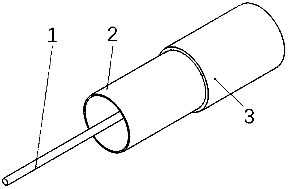
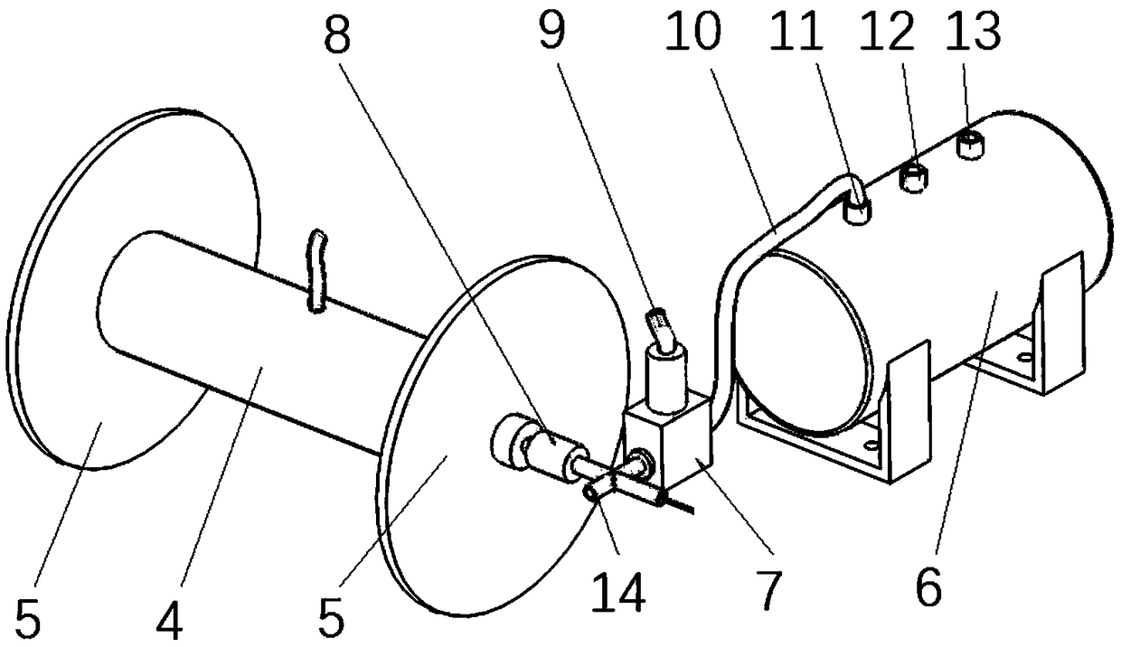
The invention relates to the technical field of spacecraft deorbiting, and discloses a spacecraft deorbiting electrodynamic tether, comprising an electrodynamic tether and a charging and degassing device, wherein the electrodynamic tether comprises a conductive wire and an elastic layer sleeved outside the conductive wire, and the charging and degassing device is connected with the electrodynamictether for charging and degassing into the elastic layer. The invention provides a spacecraft deorbiting electrodynamic tether, the elastic layer sleeved outside the conductive wire is inflated by aninflating/deflating device, so that the elastic layer becomes an air column with an internal air pressure and a certain stretching tension, thus, the electrodynamic rope becomes a rod with certain bending and torsional stiffness in space, which improves the stability of the electrodynamic rope in space, avoids the problem that the effective length of the rope decreases due to the backward folding,does not need to consider the disturbance of the axis direction of the rope, and makes the state control of the electrodynamic rope relatively simple. In addition, it is convenient to model, which makes the electrodynamic tether more convenient and concise in theoretical analysis and model operation.

Description


Claims


Application Information

Patent Timeline
Owner BEIHANG UNIV
Why Eureka
Try Eureka