Refrigeration system having adjustable refrigeration capacity

a refrigeration system and refrigeration capacity technology, applied in the direction of compression machines with several evaporators, compression machines with non-reversible cycles, lighting and heating apparatus, etc., can solve the problems of insufficient refrigeration of thermal loads, unwanted freezing of thermal loads, and insufficient refrigerating of thermal loads, so as to reduce the starting and stopping of refrigerating compressors

Inactive Publication Date: 2008-01-17
LESAGE GAETAN +1
View PDF3 Cites 12 Cited by
  • Summary
  • Abstract
  • Description
  • Claims
  • Application Information

AI Technical Summary

Benefits of technology

The present invention provides an improved refrigeration system where the amount of energy needed during start up can be controlled more smoothly. This reduces the time it takes before the compressor starts working properly. Additionally, this allows for easier control over how much work needs to be done at once.

Problems solved by technology

This patent describes a problem with current refrigeration systems that require frequent turning on and off of compressors to achieve the necessary cooling capacity while avoiding overloading certain components due to their being constantly subjected to increased temperatures during operation. Additionally, existing refrigeration systems can only provide fixed levels of refrigeration capacity based upon the amount of space they occupy. Therefore, these systems cannot efficiently accommodate varying demands without frequent stops and starts.

Method used


Image

  • Refrigeration system having adjustable refrigeration capacity
  • Refrigeration system having adjustable refrigeration capacity

Examples


Embodiment Construction

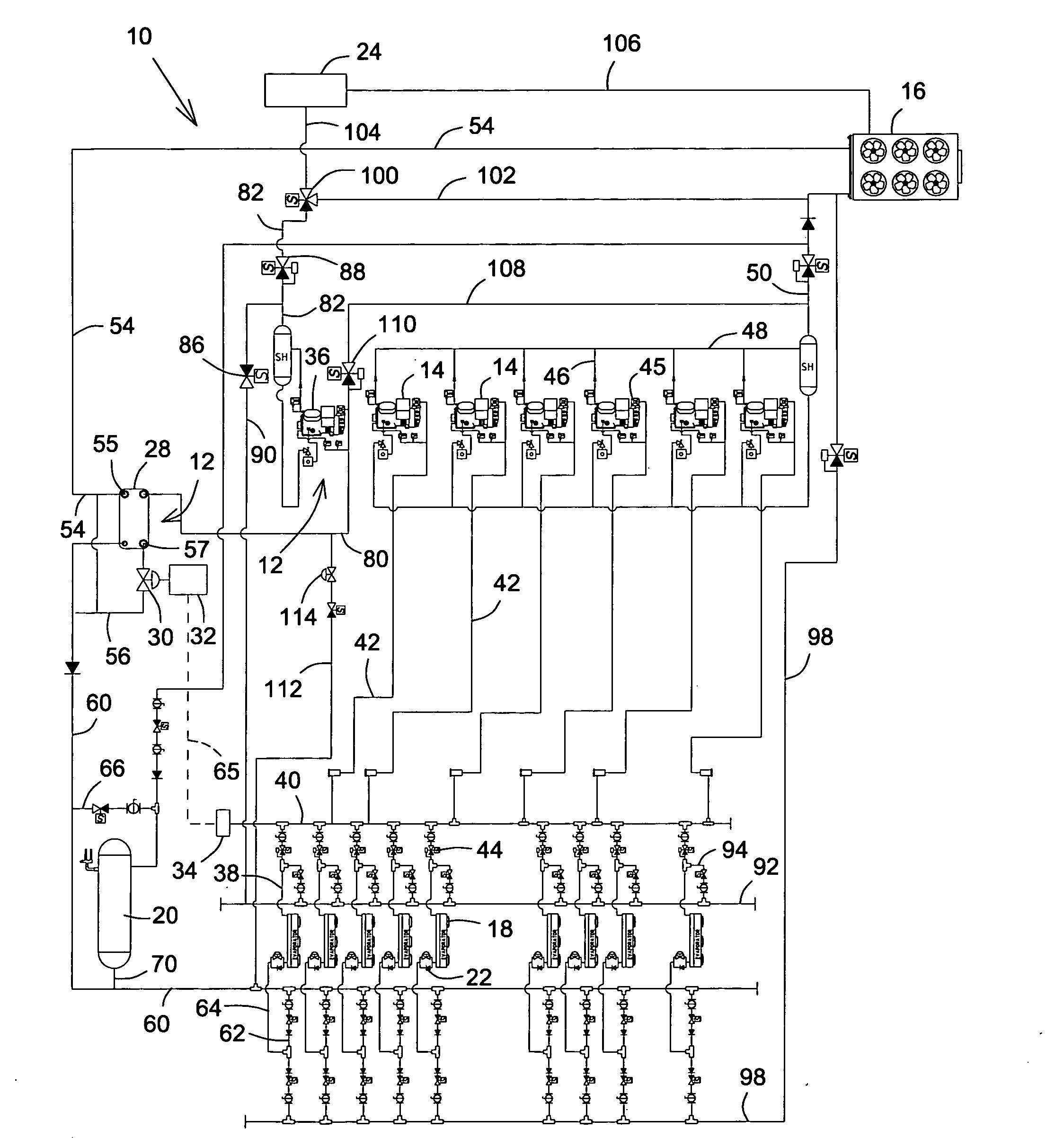
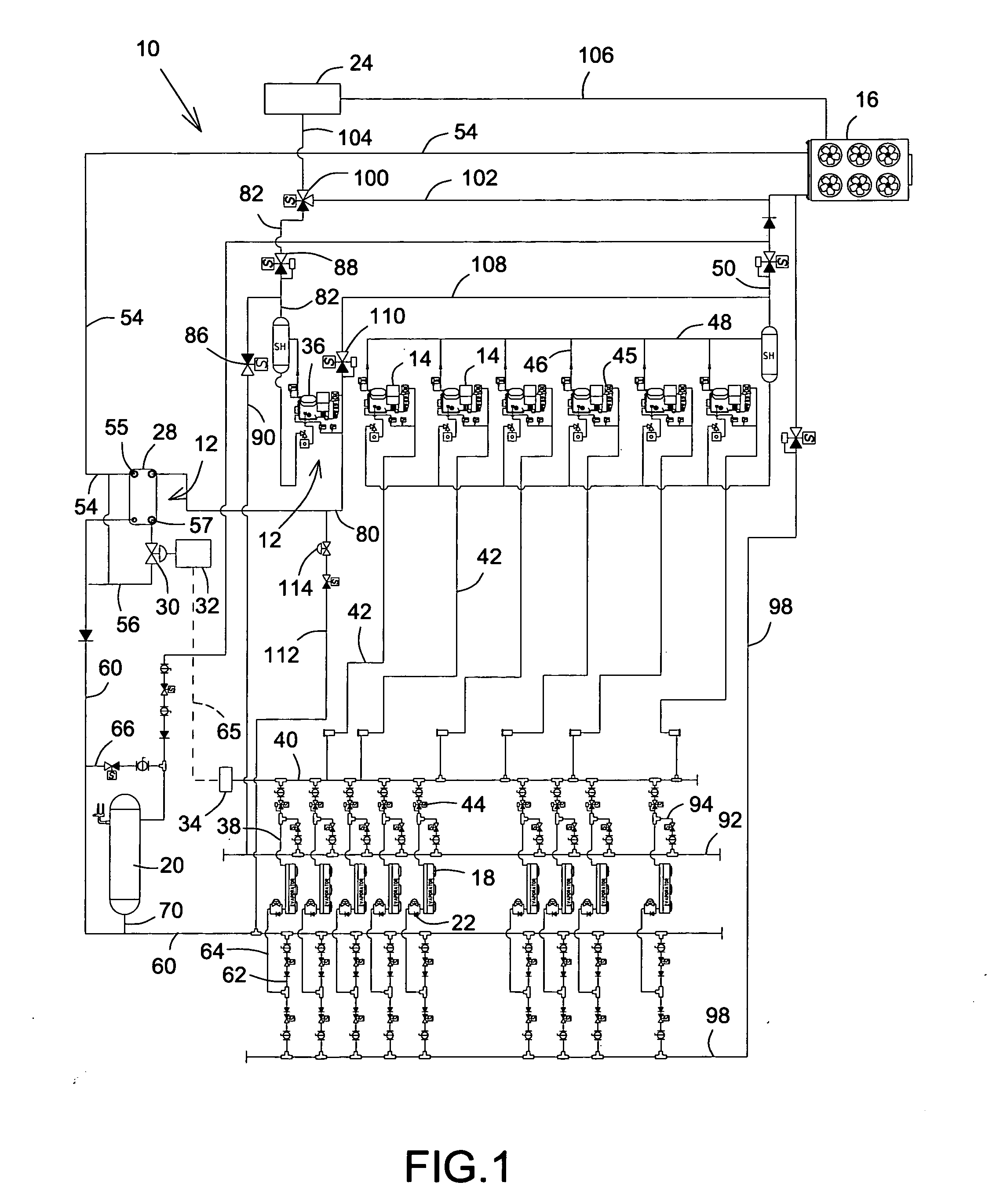
[0025]FIG. 1 is a schematic diagram of a refrigeration system, shown generally as 10, having an adjustment system, shown generally as 12, for adjusting refrigeration capacity thereof. Broadly speaking, the system 10 includes at least one, but preferably two or more, refrigerating compressors 14, adjustment system 12, an outdoor air-cooled condenser 16 as a refrigerant condensing means, at least one evaporator 18, a refrigerant liquid receiver 20, one or more refrigeration expansion valves 22, and optionally, heat reclaim means 24. System 10 also includes a plurality of conduits, also referred to as lines and manifolds, through which refrigerant is circulated in system 10 for refrigerating therewith a thermal load between refrigerating compressors 14, adjustment system 12, refrigerant condensing means 16, evaporator 18, refrigerant liquid receiver 20, refrigeration expansion valves 22, and heat reclaim means 24, all of which are connected in fluid communication for refrigerant by condui


PUM


Abstract

A subcooling heat exchanger and subcooling expansion valve in a refrigeration system provide subcooling of a pre-subcooled portion, for refrigerating a thermal load, of condensed refrigerant liquid by a pre-subcooling portion of the condensed refrigerant liquid. The amount of subcooling of the pre-subcooled portion is determined by measuring, with a pressure sensor, refrigerating suction pressure exerted by refrigerating compressors of the system. A controller then controls, based on the refrigerating suction pressure, modulation of mass of pre-subcooling portion, relative pre-subcooled portion, and expansion thereof in the subcooling expansion valve, which controls the amount of refrigerant heat exchanged, and therefore subcooling of pre-subcooled portion, between the pre-subcooling portion and the pre-subcooled portion in the subcooling heat exchanger. The pre-subcooling portion is then subsequently compressed by a subcooling compressor.

Description


Claims


Application Information

Patent Timeline
Owner LESAGE GAETAN
Why Eureka
Try Eureka