Ink jet printing apparatus
a printing apparatus and jet technology, applied in printing and other directions, can solve the problems of inability to remove the bubble in the discrete liquid chamber, insufficient ejection of ink, and blockage of the ejection port, and achieve the effect of long printing head
- Summary
- Abstract
- Description
- Claims
- Application Information
AI Technical Summary
Benefits of technology
Problems solved by technology
Method used
Image

Examples
first embodiment
(1) Description of Print Head
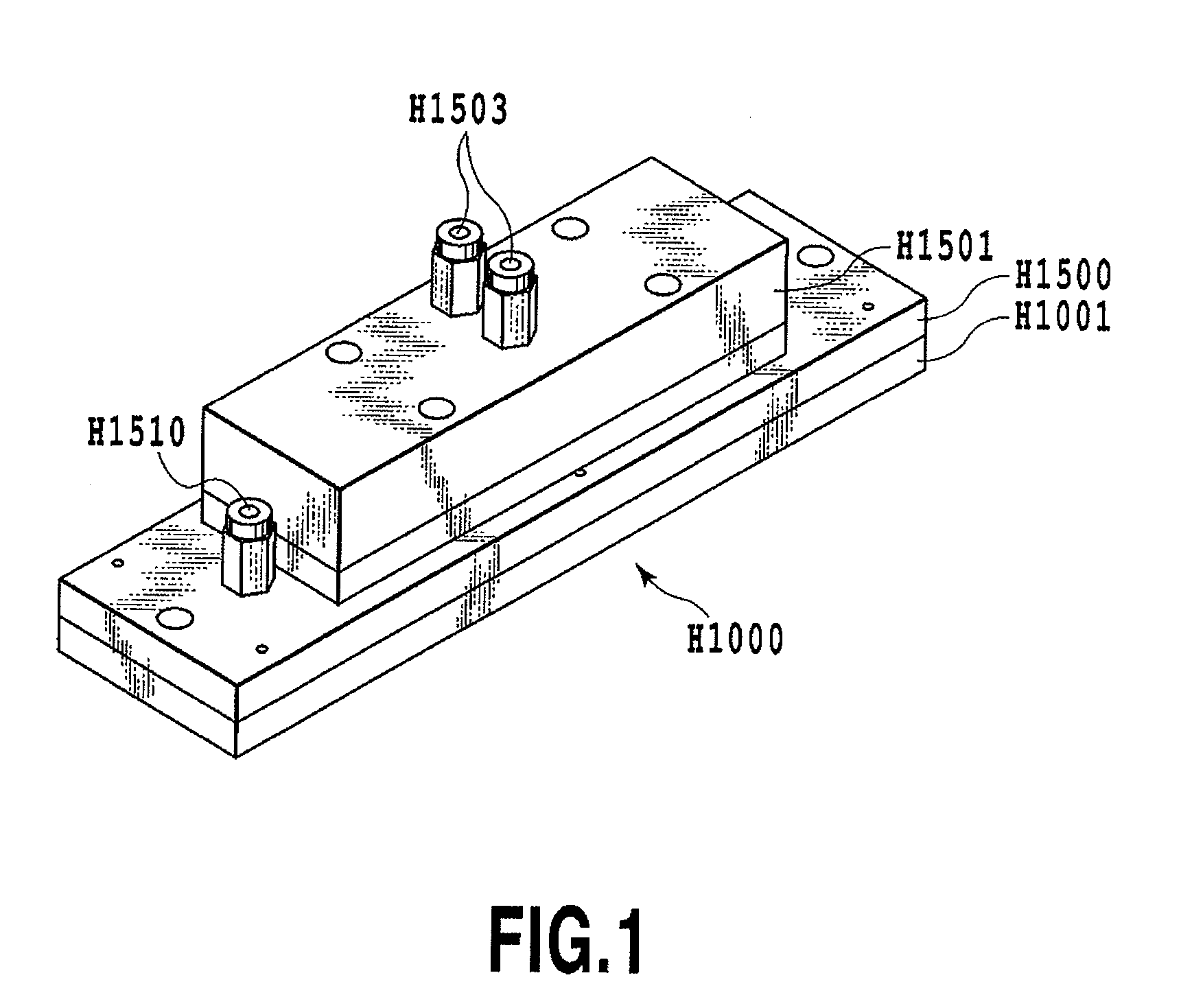
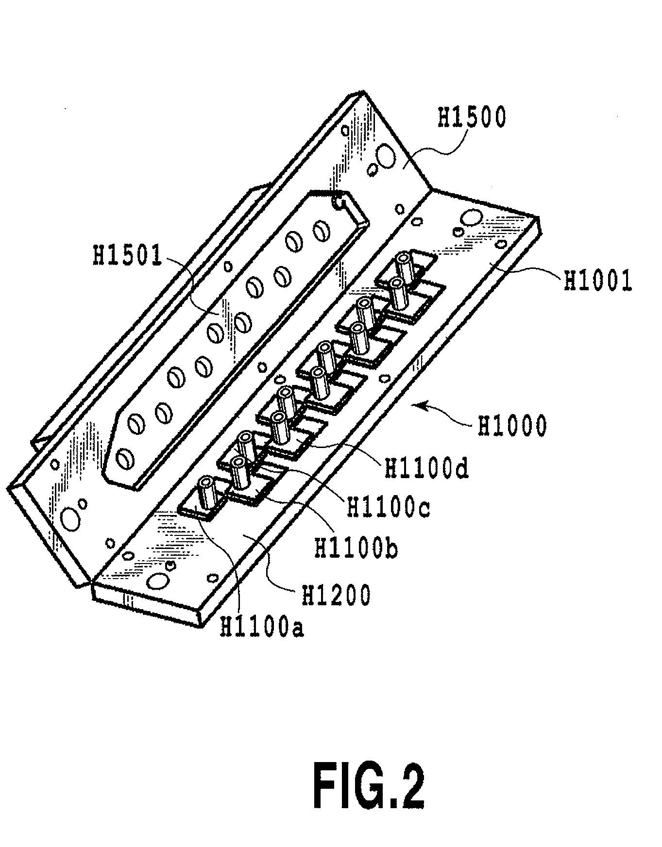
[0025]FIGS. 1 and 2 are a perspective view and an analyzed perspective view of a print head of a first embodiment of the present invention respectively.
[0026]A print head H1000 is constituted by a print element unit H1001 and an ink supplying member H1500. FIG. 1 is a perspective view showing a state where the print element unit H1001 is connected to the ink supplying member H1500. Additionally, FIG. 2 is an analyzed perspective view showing a state where the print element unit H1001 and ink supplying member H1500 of the print head H1000 shown in FIG. 1 are opened.
[0027]The print element unit H1001 is connected to the ink supplying member H1500 by, for example, positioning and fixing them with each other with a screw, sealing the fixed part with sealant, etc., and sealing up a common liquid chamber H1501. As the sealant, sealant is desirable that has ink-proof capabilities, a hardening property at normal temperatures, and flexibility for withstanding a line
second embodiment
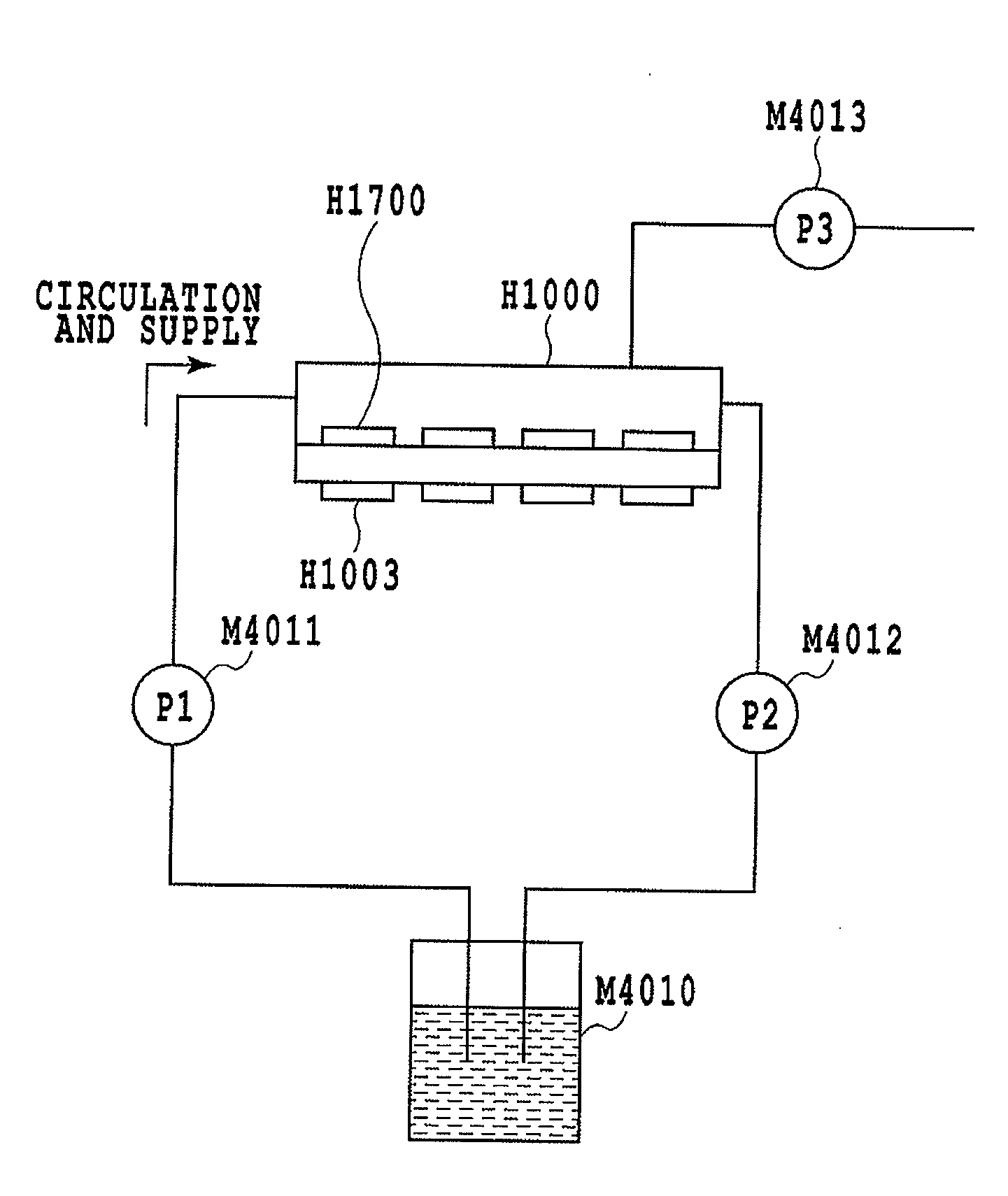
[0051]FIG. 8 is a schematic view of an ink supplying device of an ink jet printing apparatus of a second embodiment of the present invention.
[0052]In the embodiment, the circulation suction pump M4012 in the ink supplying device of the first embodiment is not used.
[0053]In the embodiment, circulation and supply of the ink into the common liquid chamber H1501 is performed by the circulation pressurization pump M4011, and simultaneously, the air suction pump M4013 is activated. As ink circulation and supply action, supplying ink / removing bubble to / from the discrete liquid chamber H1203 is performed. Here, the relationship between the flow rates P1 and P3 of the two pumps M4011 and M4013 is set to P1>P3. Thus, in removing the bubble from the discrete liquid chamber H1203, no external air is taken in from the ejection port, and the supplied ink is not discharged from the ejection port. Accordingly, no ink to be wasted from the ejection port is generated, and ink supply can be performed
third embodiment
[0054]Although the full-line type print head is described in the above embodiments, the present invention is not limited to such a print head. As shown in FIG. 9, a serial type print head used for serial method printing is applicable. In this case, as shown in FIG. 9, the circulation pressurization pump M4011 and the circulation suction pump M4012 are connected to a tube via which an ink tank H1800 is connected to the print head H1000. Additionally, the air suction pump M4013 for sucking the bubble in the discrete liquid chamber H1203 is connected to the print head H1000. The tube is shifted in accordance with a shift of the print head in a main scanning direction, and thus supplying ink / removing bubble to / from the discrete liquid chamber H1203 can be performed.
[0055]Further, the present invention is applicable to a fax machine having a copier and communication system, a word processor having a printing part, a multi-functional printer compounding the fax machine and the word proce
PUM
 Abstract
Description
Claims
Application Information
 - R&D Engineer
- R&D Manager
- IP Professional
- Industry Leading Data Capabilities
- Powerful AI technology
- Patent DNA Extraction
Browse by: Latest US Patents, China's latest patents, Technical Efficacy Thesaurus, Application Domain, Technology Topic.
© 2024 PatSnap. All rights reserved.Legal|Privacy policy|Modern Slavery Act Transparency Statement|Sitemap