Self-contouring spinal rod

Inactive Publication Date: 2008-04-17
AESCULAP AG
View PDF28 Cites 63 Cited by
  • Summary
  • Abstract
  • Description
  • Claims
  • Application Information

AI Technical Summary

Problems solved by technology

However, one problem with a conventional spinal rod is that the rigidity of the rod makes contouring the rod difficult and time consuming to insert into the spine.
Another problem with conventional spinal rods is the inability to perform multiple level fusions through a minimally invasive approach.
Still another problem with conventional spinal rods is that the required contouring of the rod to meet patient anatomy often creates a non-uniform bend or bends (i.e. kinks) that decrease the strength of the rod.
However, the natural anatomy of the spine does not allow hooks and screws to be connected in a straight line.
In addition, the pedicies vary in location and angle

Method used


Image

  • Self-contouring spinal rod
  • Self-contouring spinal rod
  • Self-contouring spinal rod

Examples


Embodiment Construction

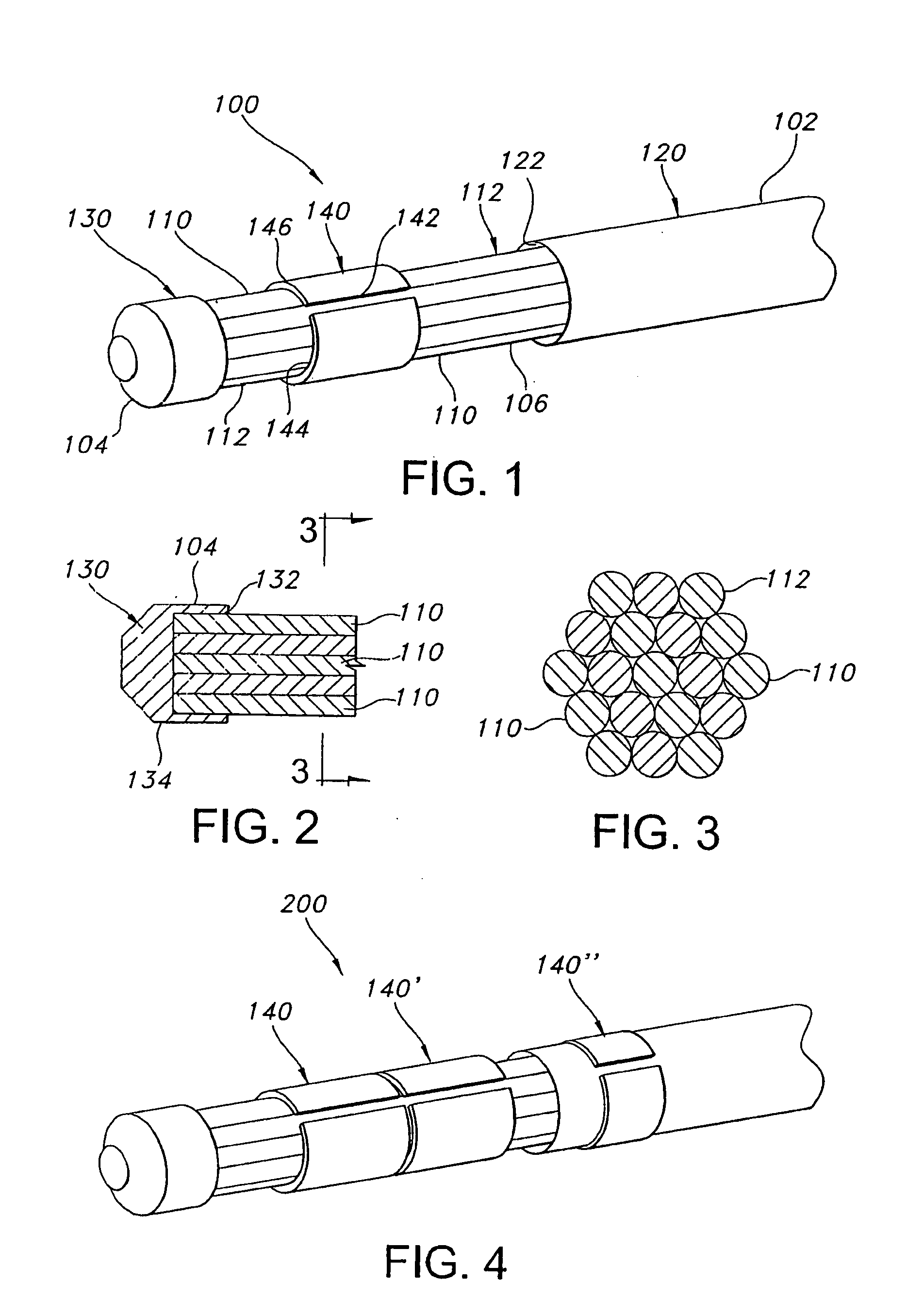
[0028] Certain terminology is used herein for convenience only and is not to be taken as a limitation on the present invention. The terminology includes the words specifically mentioned, derivatives thereof and words of similar import. As used herein, the term “distal” is defined to mean a direction closer to a tip of a rod assembly as described herein and “proximal” is defined to mean a direction farther from the tip of the rod assembly as described herein. Further, the term “rod element” may mean wires, shafts, and bars, or any other elongated device, in addition to rods. The following describes preferred embodiments of the invention. However, it should be understood based on this disclosure, that the invention is not limited by the preferred embodiments of the invention.

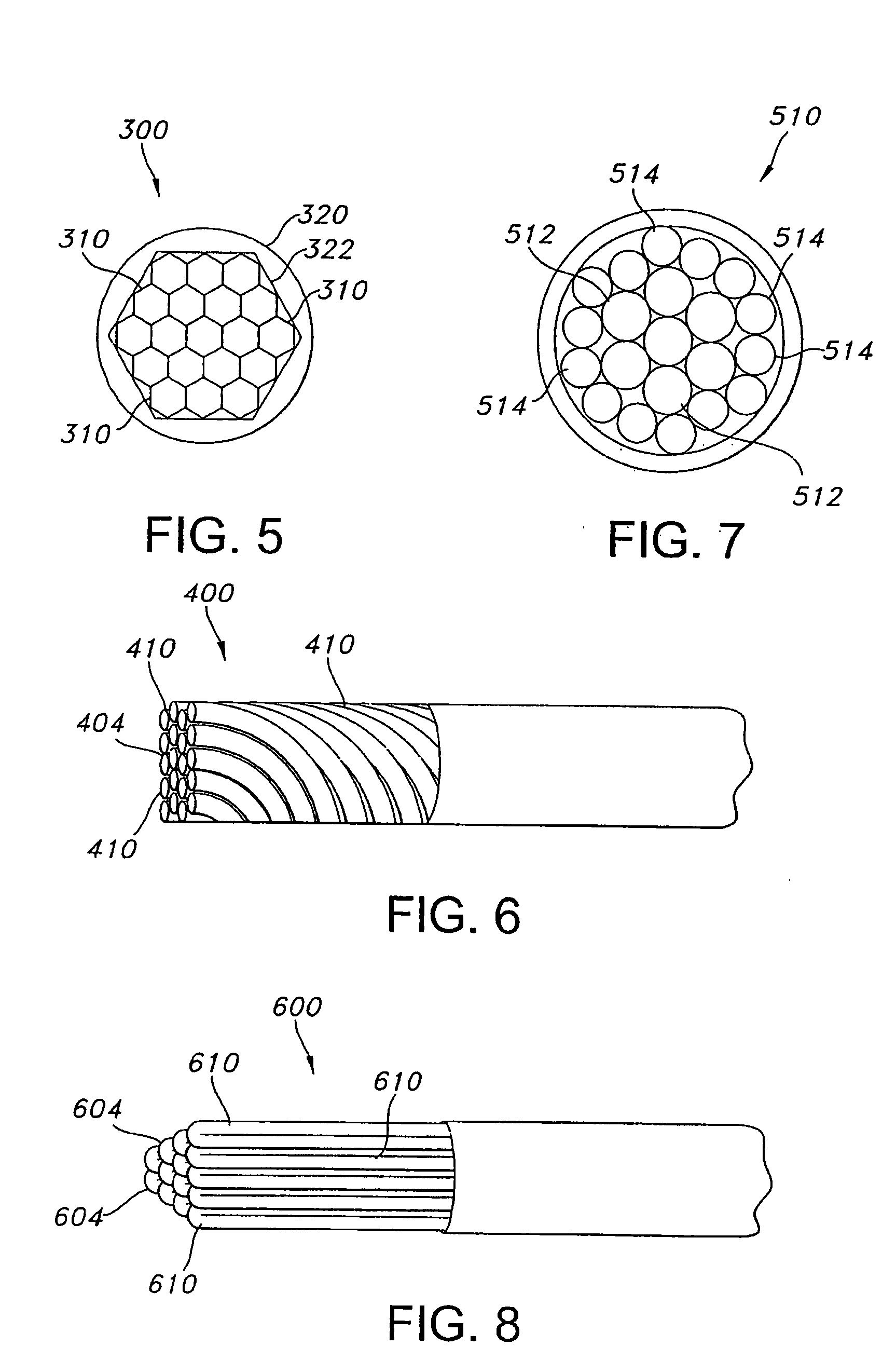
[0029] Referring to the Figures generally, a self-contouring spinal rod assembly is shown. The rod assembly is used in a spinal implant to support the spinal implant. The rod assembly is inserted into a screw, a hoo


PUM


Abstract

A self-contouring spinal rod assembly. The assembly has a proximal end, a distal end, and a length extending between the proximal end and the distal end. A plurality of rod elements extend along the length, such that each of the plurality of rod elements is in contact with an adjacent rod element. The plurality of rod elements are fixed against movement relative to each other at the distal end. The plurality of rod elements are movable relative to each other along a length proximal the distal end. A method of assembling the spinal rod assembly is also provided.

Description


Claims


Application Information

Patent Timeline
Owner AESCULAP AG
Why Eureka
Try Eureka