Customizing an intervertebral implant

a technology of intervertebral implants and custom designs, applied in the field of customizing intervertebral implants, can solve problems such as damage to vertebrae, and achieve the effect of eliminating as far as possibl

Active Publication Date: 2006-12-14
DEPUY SYNTHES PROD INC
View PDF35 Cites 55 Cited by
  • Summary
  • Abstract
  • Description
  • Claims
  • Application Information

AI Technical Summary

Benefits of technology

The present invention provides a custom-designed spinal implant that can be inserted into any irregularly shaped space within the body. These spaces may include cervicles, lamina, facet joints, or other bones. By adjusting the distance between these structures, it becomes easier to create a prosthetic device that matches the natural curvature of the structure being replaced. Additionally, the implant can contain various features like cushions or inserts that help reduce pain caused by degenerative processes. Overall, this technology allows for precise placement of the implants while minimizing their risk of causing damage during surgery.

Problems solved by technology

The technical problem addressed in this patent text is how to treat patients who suffer from a breakage or damage of one or both cervical and thoracic spines without requiring fusion procedures that can cause complications.

Method used


Image

  • Customizing an intervertebral implant
  • Customizing an intervertebral implant
  • Customizing an intervertebral implant

Examples


Embodiment Construction

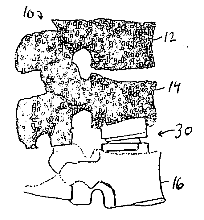
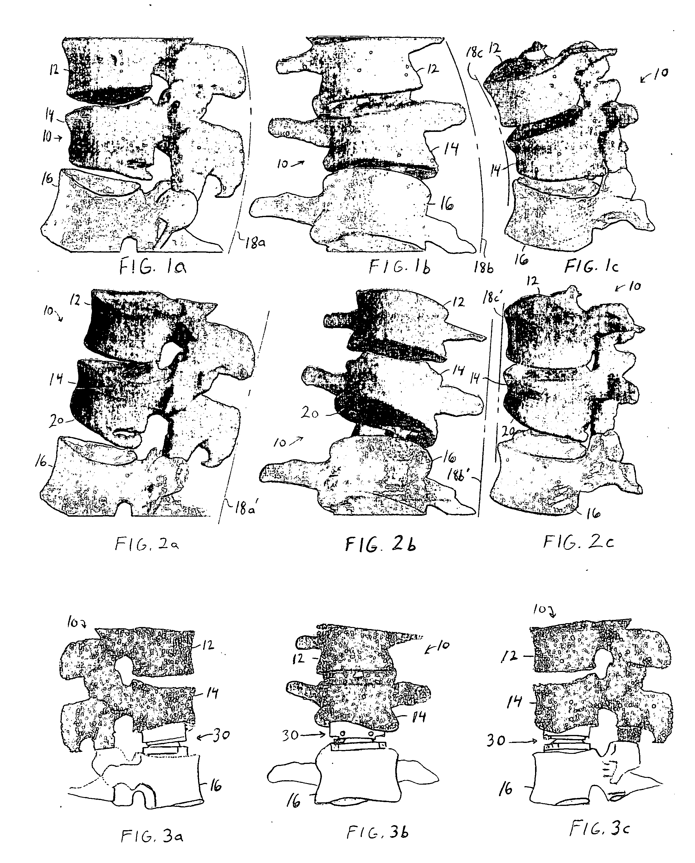
[0029] As noted above, the present invention is useful with either a damaged vertebra or, where appropriate or where a disc replacement is otherwise being made, with malformed vertebra. Where the present invention is used with malformed vertebrae, it will be appreciated that there will be a targeted vertebra whose abnormality is being compensated for or two adjacent targeted vertebra whose common disc is being replaced. While the targeted vertebra (or adjacent vertebrae) may contribute only to a part of the overall deformed curvature as in scoliosis, correction of that vertebra (or vertebrae) may be desired to reduce the overall curvature and achieve a meaningful improvement in the undesired curvature. In such a case, the targeted vertebra or both targeted vertebrae on either side of the disc being replaced may be overcompensated for in order to help correct the undesired curvature of the adjacent vertebra. For convenience, this overcompensation will still be referred to as “natural” e


PUM


Abstract

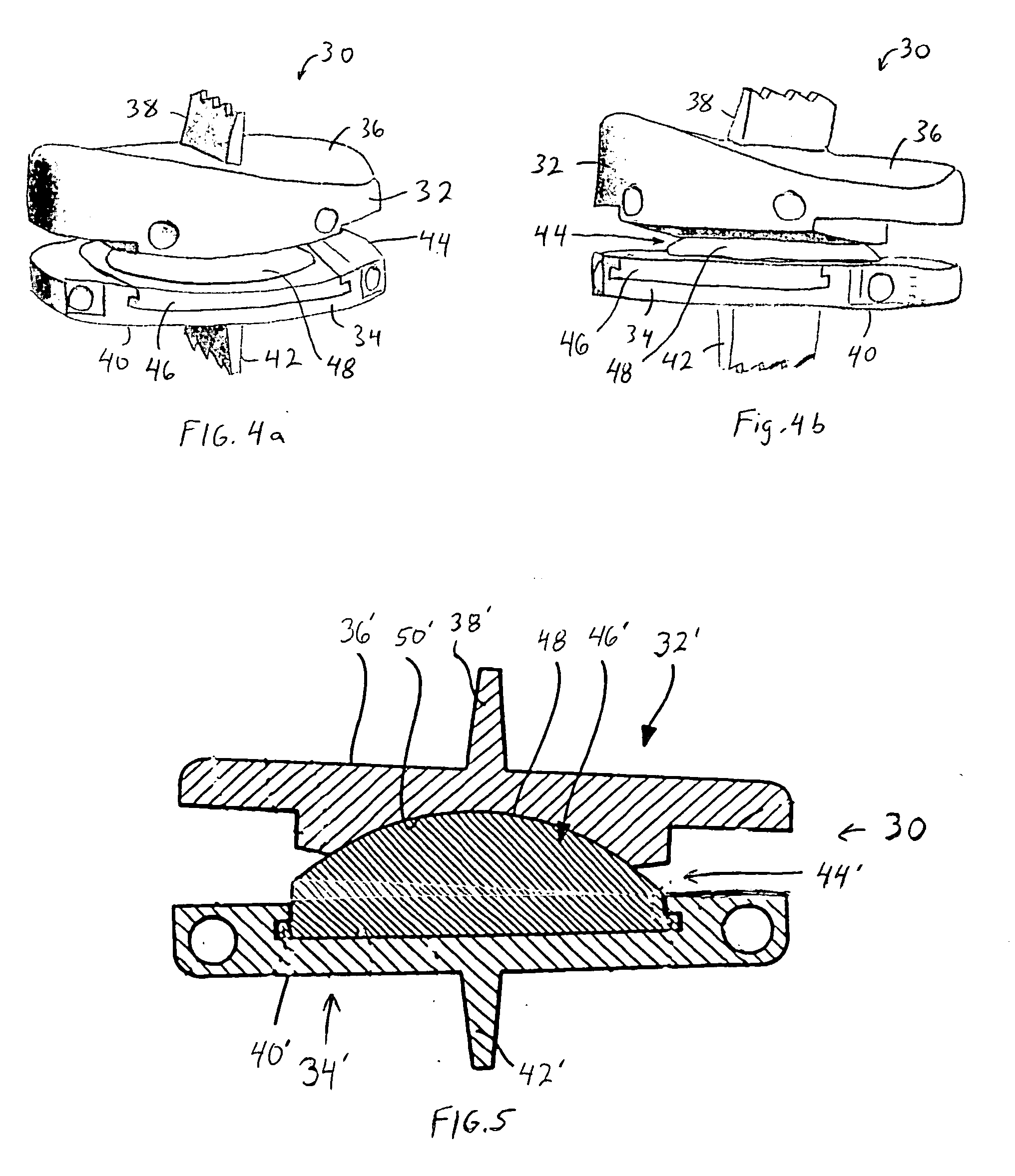
A method and apparatus for customizing an intervertebral implant includes the initial step of obtaining a 3D anatomy of a series of vertebrae including an abnormal vertebra in a computer. The 3D anatomy of the series is then repositioned in the computer to eliminate the deformity caused by the abnormal vertebra. It is next determined whether a superior or inferior surface of the abnormal vertebra is an abnormal surface which causes the deformity, whereby an approximate gap between the abnormal surface and a desired normal surface is determined. Using that gap determination, a custom implant is constructed to engage the abnormal surface and fill the determined gap. Thus, when the implant is implanted between the abnormal surface and an adjacent surface of an adjacent vertebrae, the deformity is substantially compensated for. The implant may have articulation between the endplates to allow relative movement therebetween.

Description


Claims


Application Information

Patent Timeline
Owner DEPUY SYNTHES PROD INC
Why Eureka
Try Eureka