Coupling assembly for coupling a rod to a bone anchoring element, kit of such a coupling assembly different rod receiving elements and bone anchoring device

Active Publication Date: 2015-01-29
BIEDERMANN TECH GMBH & CO KG
View PDF5 Cites 60 Cited by
  • Summary
  • Abstract
  • Description
  • Claims
  • Application Information

AI Technical Summary

Benefits of technology

The invention provides an improved coupling assembly for connecting a rod to a bone anchor and a bottom loading polyaxial bone anchoring device that is easier to handle and has a wider range of applications. The pressure element of the device has a slit ring at its bottom end, which expands in a radial direction to facilitate the insertion of the anchor head. This reduces the force required to insert the anchor head and simplifies the handling during surgery. The bone anchoring device can be part of a modular system that allows for various combinations of different bone anchoring elements and rods, providing greater flexibility and reducing costs for stock-keeping.

Problems solved by technology

This enlarges the field of application of the bone anchoring device.

Method used


Image

  • Coupling assembly for coupling a rod to a bone anchoring element, kit of such a coupling assembly different rod receiving elements and bone anchoring device
  • Coupling assembly for coupling a rod to a bone anchoring element, kit of such a coupling assembly different rod receiving elements and bone anchoring device
  • Coupling assembly for coupling a rod to a bone anchoring element, kit of such a coupling assembly different rod receiving elements and bone anchoring device

Examples


first embodiment

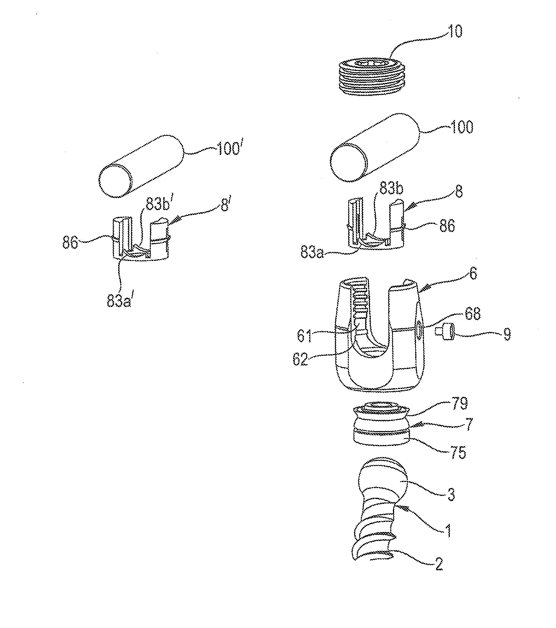
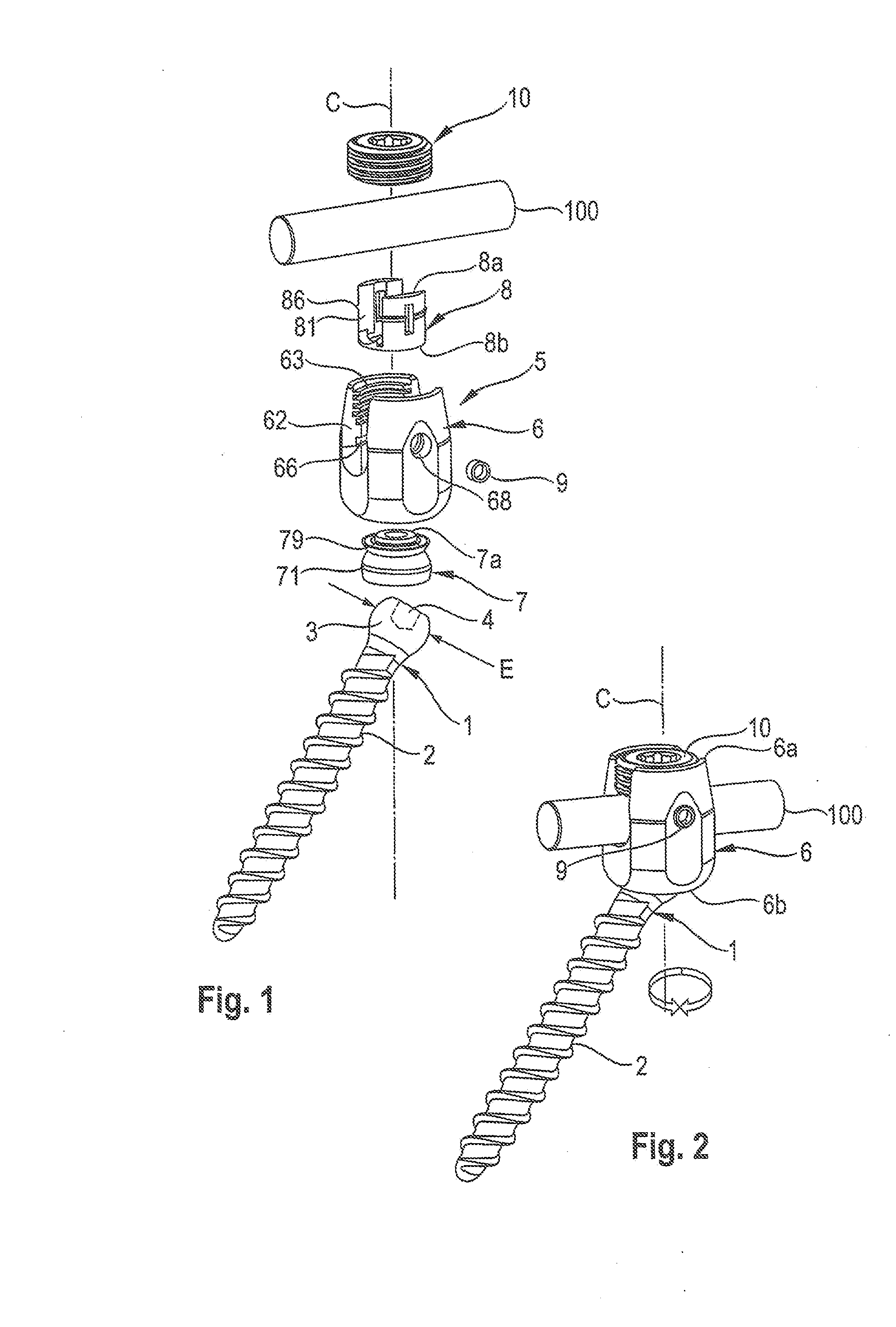
[0050]In FIGS. 1 and 2, a bone anchoring device includes a bone anchoring element 1 in the form of a bone screw having a shank 2 that is at least partially provided with a bone thread and a head 3. The head 3 has a spherical segment-shaped outer surface portion including a greatest outer diameter E of the sphere and a flat free end with a recess 4 for engagement with a screwing-in tool.

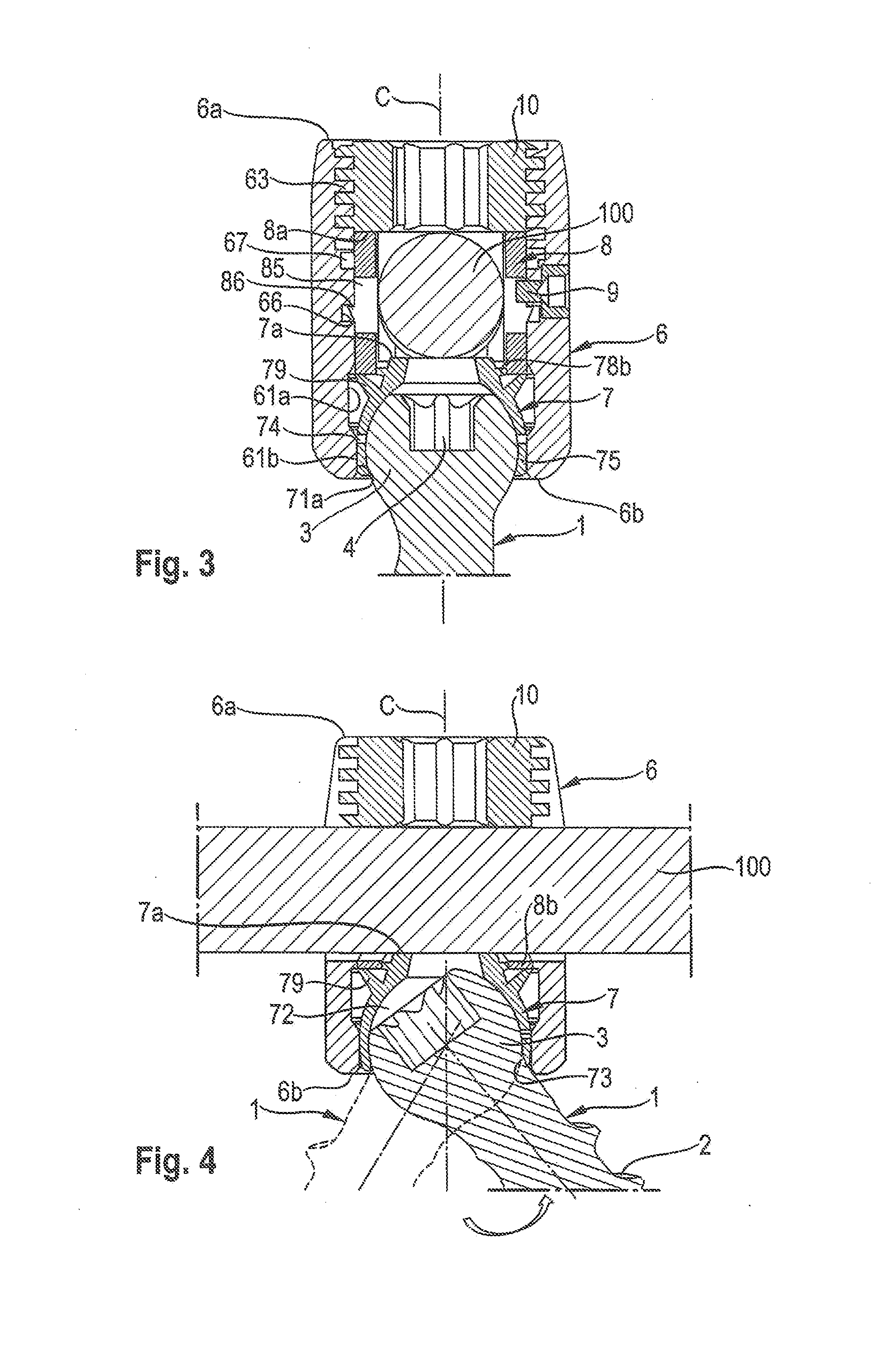
[0051]The bone anchoring device further includes a coupling assembly 5 for receiving a stabilization rod 100 and for coupling the stabilization rod 100 to the bone anchoring element 1. The coupling assembly 5 includes a receiving part 6 for receiving the head 3 of the bone anchoring element 1 and for receiving the rod 100, a pressure element 7 configured to be arranged in the receiving part 6 and a rod receiving element 8 also configured to be arranged in the receiving part 6. The pressure element 7 serves for locking the head 3 in the receiving part 6. The rod receiving element 8 serves for receivin...

second embodiment

[0088]the coupling assembly is described with reference to FIG. 30. FIG. 30 shows the bone anchoring device with the anchoring element 1, the rod 100 and the locking element 10 as in the previous embodiments. The pressure element 700 differs from the pressure element of the previous embodiments in that it is free from a deformable portion that cooperates with the rod receiving element and does not have the annular projection for connecting it in an interference-fit manner to the rod receiving element. Instead of this, the pressure element 700 comprises a non-deformable annular projection 790 with a flat upper surface 790a that cooperates with a collar-like conically widening projection 890 at the second end of the rod receiving element 800. The collar like projection 890 has a substantially inverse shape compared to the collar 79 as described in the previous embodiments. It is slightly flexible when it engages the flat upper surface 790a of the pressure element 700 when a load acts ...


PUM


Abstract

An instrument for inserting a bone anchoring element into a bone is provided, the instrument including a shaft (2) having an end portion (23, 23′) for engaging the bone anchoring element and for transferring torque to the bone anchoring element (1, 1′) and a longitudinal axis defining an axis of rotation (R);a cutting member (4, 4′) connected to the shaft (2) with cutting portions (45) that are configured to cut bone material;wherein the cutting member (4, 4′) has an outer diameter (D) defined by the cutting portions (45) that is substantially the same or larger than an outer diameter (dd) of a receiving part (500) of the polyaxial bone anchor in a region at a bottom end (500b) of the receiving part.

Description

CROSS-REFERENCE TO RELATED APPLICATION(S)[0001]The present application claims priority to and the benefit of U.S. Provisional Patent Application Ser. No. 61 / 858,026, filed Jul. 24, 2013, the contents of which are hereby incorporated by reference in their entirety, and claims priority from European Patent Application EP 13 177 919.1, filed Jul. 24, 2013, the contents of which are hereby incorporated by reference in their entirety.BACKGROUND[0002]1. Field[0003]The invention relates to a coupling assembly for coupling a rod to a bone anchoring element, wherein the coupling assembly comprises a receiving part with a recess for receiving the rod and an accommodation space for accommodating a head of the bone anchoring element and further with a pressure element to clamp the head and with a rod receiving element that cooperates with the pressure element. The pressure element and the rod receiving element are configured to cooperate in such a way that when the anchoring element is inserted...

Claims


Application Information

Patent Timeline
IPC IPC(8): A61B17/70
CPCA61B17/7035A61B17/7032A61B17/7037A61B2017/567A61B2017/681
Inventor BIEDERMANN, LUTZMATTHIS, WILFRIEDFISCHER, BERND
Owner BIEDERMANN TECH GMBH & CO KG
Why Eureka
Try Eureka