Inrush current restraining circuit and audio device using the same

Inactive Publication Date: 2008-05-08
HON HAI PRECISION IND CO LTD
View PDF10 Cites 1 Cited by
  • Summary
  • Abstract
  • Description
  • Claims
  • Application Information

AI Technical Summary

Benefits of technology

[0005]A exemplary embodiment of the present invention provides an inrush current restraining circuit, which includes a power source, a charging/discharging circuit, a switching circuit, a first impedance component, a second impedance component and a controller. The charging/discharging circuit is connected to the power source. An input of the switching circuit is connected to the charging/discharging circuit, and an outp

Problems solved by technology

When the inrush current flows to an earphone or loudspeaker, a loud poppin

Method used


Image

  • Inrush current restraining circuit and audio device using the same
  • Inrush current restraining circuit and audio device using the same
  • Inrush current restraining circuit and audio device using the same

Examples


Embodiment Construction

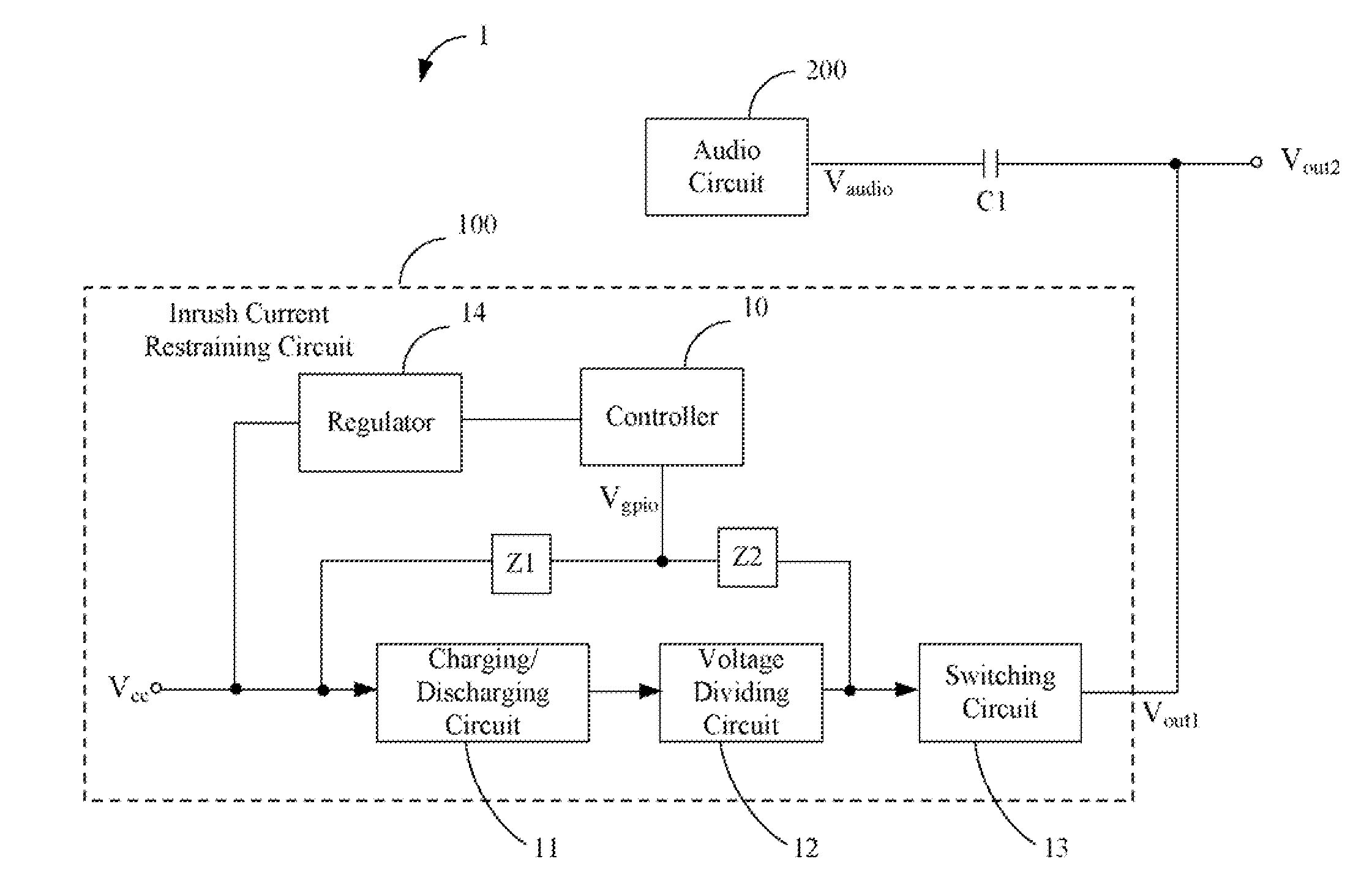
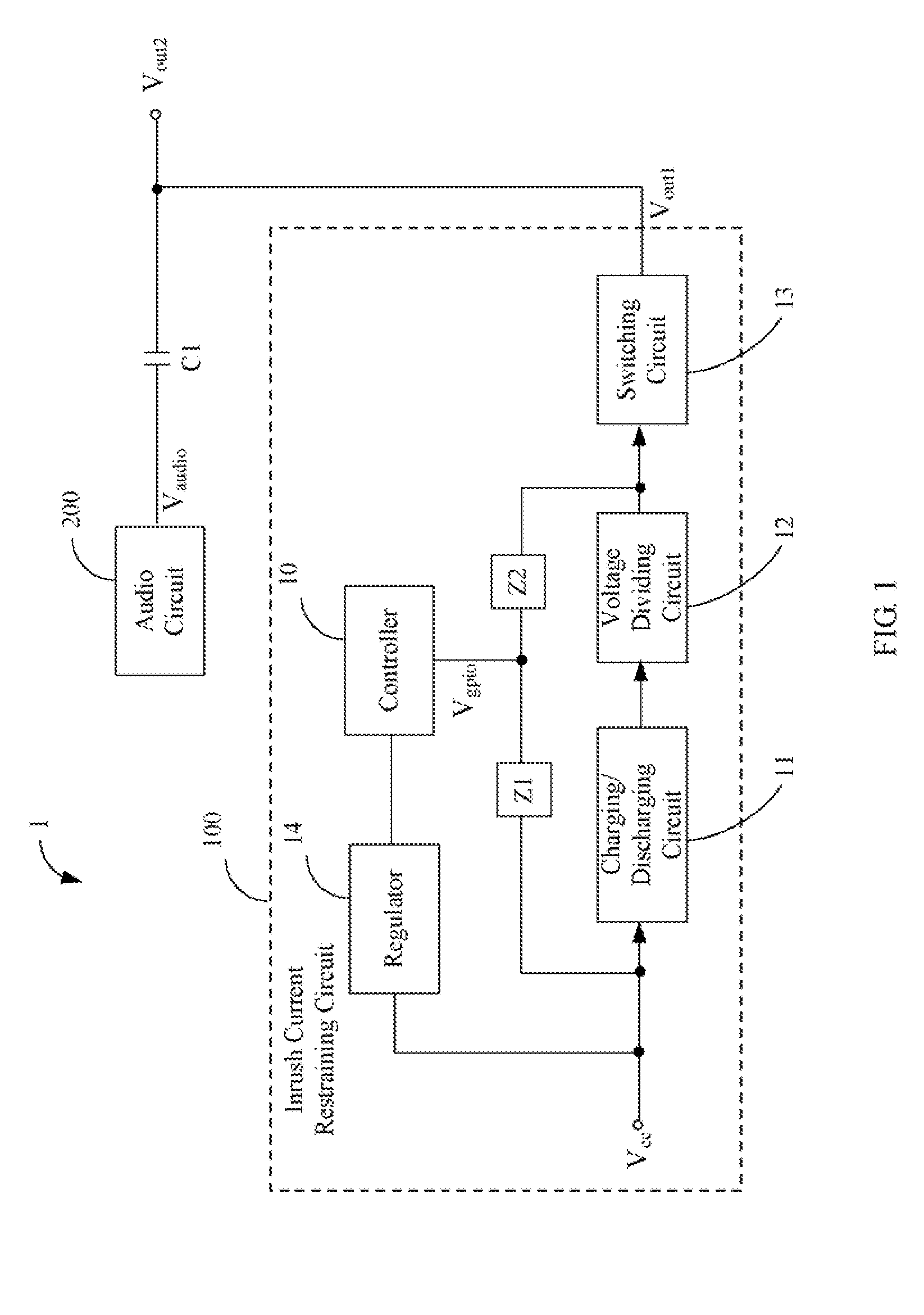
[0011]FIG. 1 is a block diagram of an audio device 1 of an exemplary embodiment of the present invention. The audio device 1 includes an audio circuit 200, a DC-blocking capacitor C1, and an inrush current restraining circuit 100. The inrush current restraining circuit 100 is connected to the audio circuit 200 via the DC-blocking capacitor C1, for restraining inrush current generated by the audio device 1. The audio circuit 200 includes a power source Vcc, a controller 10, a charging / discharging circuit 11, a voltage dividing circuit 12, a switching circuit 13, a regulator 14, a first impedance Z1 and a second impedance Z2.

[0012]The audio circuit 200 outputs an audio signal Vaudio. The DC-blocking capacitor C1 is used for blocking a DC component of the audio signal Vaudio output from the audio circuit 200, and the audio signal Vaudio without the DC component is defined as output Vout2 of the audio device 1. However, inrush current is generated due to a capacitance effect when the aud


PUM


Abstract

An inrush current restraining circuit (100) includes a power source (Vcc), a charging/discharging circuit (11), a switching circuit (13), a first impedance component (Z1), a second impedance component (Z2), and a controller (10). The charging/discharging circuit is connected to the power source. An input of the switching circuit is connected to the charging/discharging circuit, and an output of the switching circuit is defined as an output of the inrush current restraining circuit. One end of the first impedance component is connected to the power source. The second impedance component is connected between the other end of the first impedance and the switching circuit. The controller is connected a joint of the first impedance component and the second impedance component, for providing a control signal.

Description


Claims


Application Information

Patent Timeline
Owner HON HAI PRECISION IND CO LTD
Why Eureka
Try Eureka