Method and apparatus for RF input coupling for inductive output tubes and other emission gated devices

Active Publication Date: 2008-05-29
L3 TECH INC
View PDF11 Cites 5 Cited by
  • Summary
  • Abstract
  • Description
  • Claims
  • Application Information

AI Technical Summary

Benefits of technology

[0013]In both of these topologies, the impedance mismatch between the coaxial transmission line and the resonant cavity can be tuned by employing several techniques. First, an iris can be positioned at the location where the outer conductor of the coaxial transmission line joins the resonant cavity. The iris has an opening with a diameter that is smaller than that of the outer conductor of the transmission line but larger than the diameter of the center conductor, allowing the center conductor to pass t

Problems solved by technology

Practical limits on the loop size prevent subst

Method used


Image

  • Method and apparatus for RF input coupling for inductive output tubes and other emission gated devices
  • Method and apparatus for RF input coupling for inductive output tubes and other emission gated devices
  • Method and apparatus for RF input coupling for inductive output tubes and other emission gated devices

Examples


Embodiment Construction

[0026]The invention provides improved instantaneous bandwidth of the input circuit of an IOT or other density-modulated device. In the detailed description that follows, like numbers are used to describe like elements illustrated in one or more of the figures.

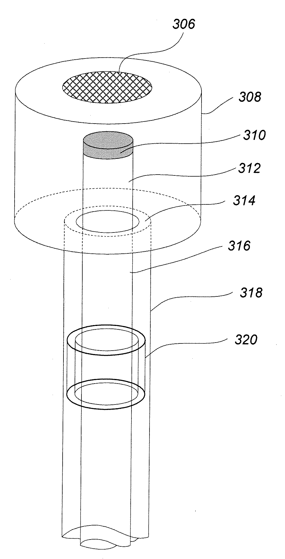
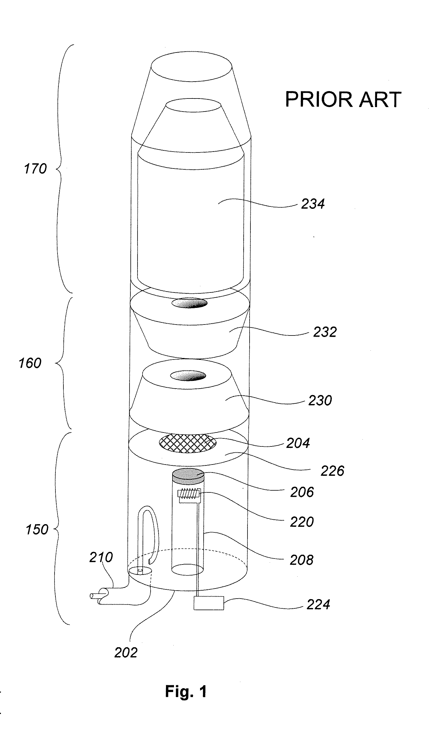
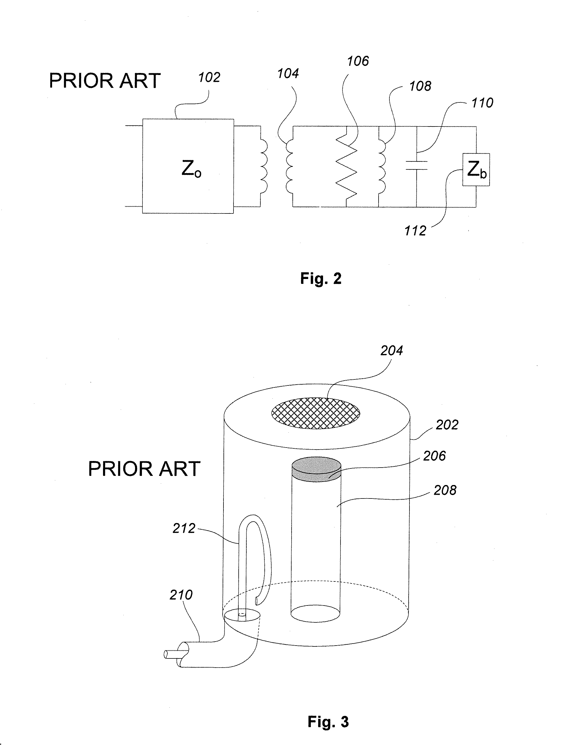
[0027]FIG. 1 is a schematic drawing of an exemplary IOT, typical of the prior art. The IOT includes three major sections, including an electron gun 150, a tube body 160, and a collector 170. The electron gun 150, shown in more detail in FIG. 3, provides an axially directed electron beam that is density modulated by an RF signal. The electron beam passes through a first drift tube 230 and a second drift tube 232 and then passes into an inner structure 234 inside the collector 170 that collects the spent electron beam. The electron gun further includes a cathode 206 with a closely spaced control grid 204. The cathode is disposed at the end of a cylindrical capsule 208 that includes an internal heater coil 220 coupled to a heater vol


PUM


Abstract

An input circuit of a microwave amplification tube achieves improved instantaneous bandwidth. By directly coupling the transmission line carrying a modulating radio frequency signal to a control grid, a low-Q input circuit is created that increases the fractional bandwidth of the system. A resonant cavity may be used to generate a voltage across the gap between the cathode and the control grid. Alternative geometries are presented whereby the electron beam is emitted from a cathode connected either to the center conductor of the transmission line or to the outer conductor of the transmission line. Alternatively, the electric field of the radio-frequency signal propagating through the transmission line may be used to create a voltage across the gap between the cathode and the control grid without using a resonant cavity. Likewise, alternative geometries are presented by which the electron beam is emitted from a cathode connected either to the center conductor or to the outer conductor of the transmission line.

Description


Claims


Application Information

Patent Timeline
Owner L3 TECH INC
Why Eureka
Try Eureka