Detection device, method and program thereof

Inactive Publication Date: 2008-08-21
ORMON CORP
View PDF5 Cites 87 Cited by
  • Summary
  • Abstract
  • Description
  • Claims
  • Application Information

AI Technical Summary

Benefits of technology

[0031]According to the aspects of the present invention, it is possible to detect a rotational movement component of a camera mounted on a mobile object. In particular, accord

Problems solved by technology

However, it cannot be said that the detection precision of detecting a rotational movement component of a vehicle by the conventional yaw rate sensor is sufficient.
As a result, there is a fear of deteriorating the detection precision of a moving object.
In addition, in the case of correcting the optical fl

Method used


Image

  • Detection device, method and program thereof
  • Detection device, method and program thereof
  • Detection device, method and program thereof

Examples


second embodiment

[0253]First, the rotation angle detecting portion 165 will be described with reference to FIGS. 28 and 29.

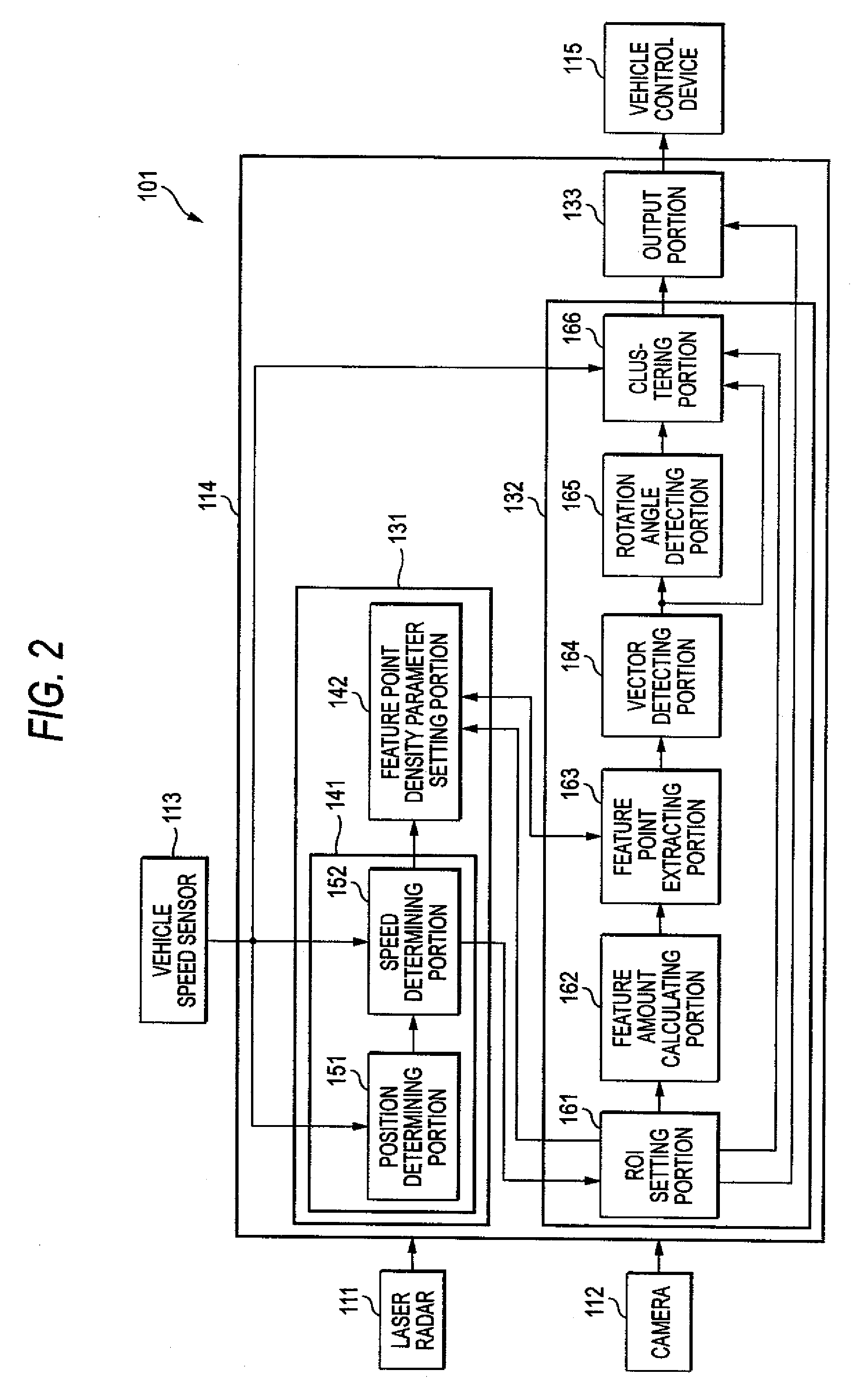
[0254]FIG. 28 is a block diagram showing a functional construction of a second embodiment of the rotation angle detecting portion 165. The rotation angle detecting portion 165 shown in FIG. 28 detects the rotation angle of the camera 112 by the combined use of the least-squares method and the RANSAC, one of the robust estimation techniques. The rotation angle detecting portion 165 shown in FIG. 28 is configured to include a rotation angle calculating portion 241, an error calculating portion 242, a selecting portion 421, and a rotation angle estimating portion 422. In the drawing, portions corresponding to those of FIG. 5 will be denoted by the same reference numerals, and repeated descriptions will be omitted for the processes that are identical to those of FIG. 5.

[0255]Like the selecting portion 243 of FIG. 5, the selecting portion 421 selects one of the temporary rotation angles

third embodiment

[0262]Next, the rotation angle detecting portion 165 will be described with reference to FIGS. 30 and 31.

[0263]FIG. 30 is a block diagram showing a functional construction of a third embodiment of the rotation angle detecting portion 165. The rotation angle detecting portion 165 shown in FIG. 30 detects the rotation angle of the camera 112 by the use of the Hough transform, one of the robust estimation techniques. The rotation angle detecting portion 165 shown in FIG. 30 is configured to include a Hough transform portion 441 and an extracting portion 442.

[0264]The Hough transform portion 441 acquires information representing the detected motion vector from the vector detecting portion 164. As will be described with reference to FIG. 31, the Hough transform portion 441 performs a Hough transform on the above-described expression (11) for the motion vector detected by the vector detecting portion 164 and supplies information representing the results of the Hough transform to the extracti


PUM


Abstract

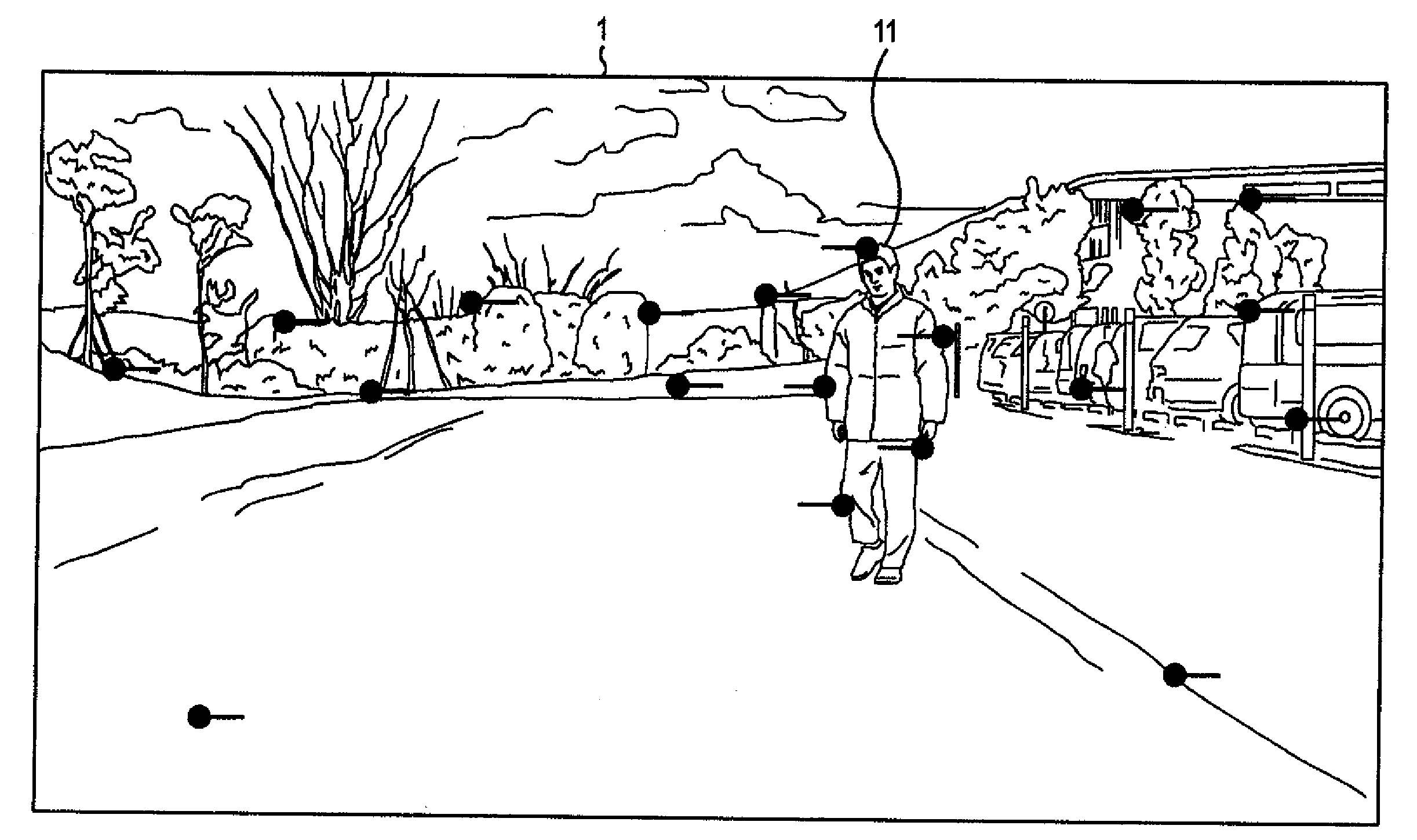
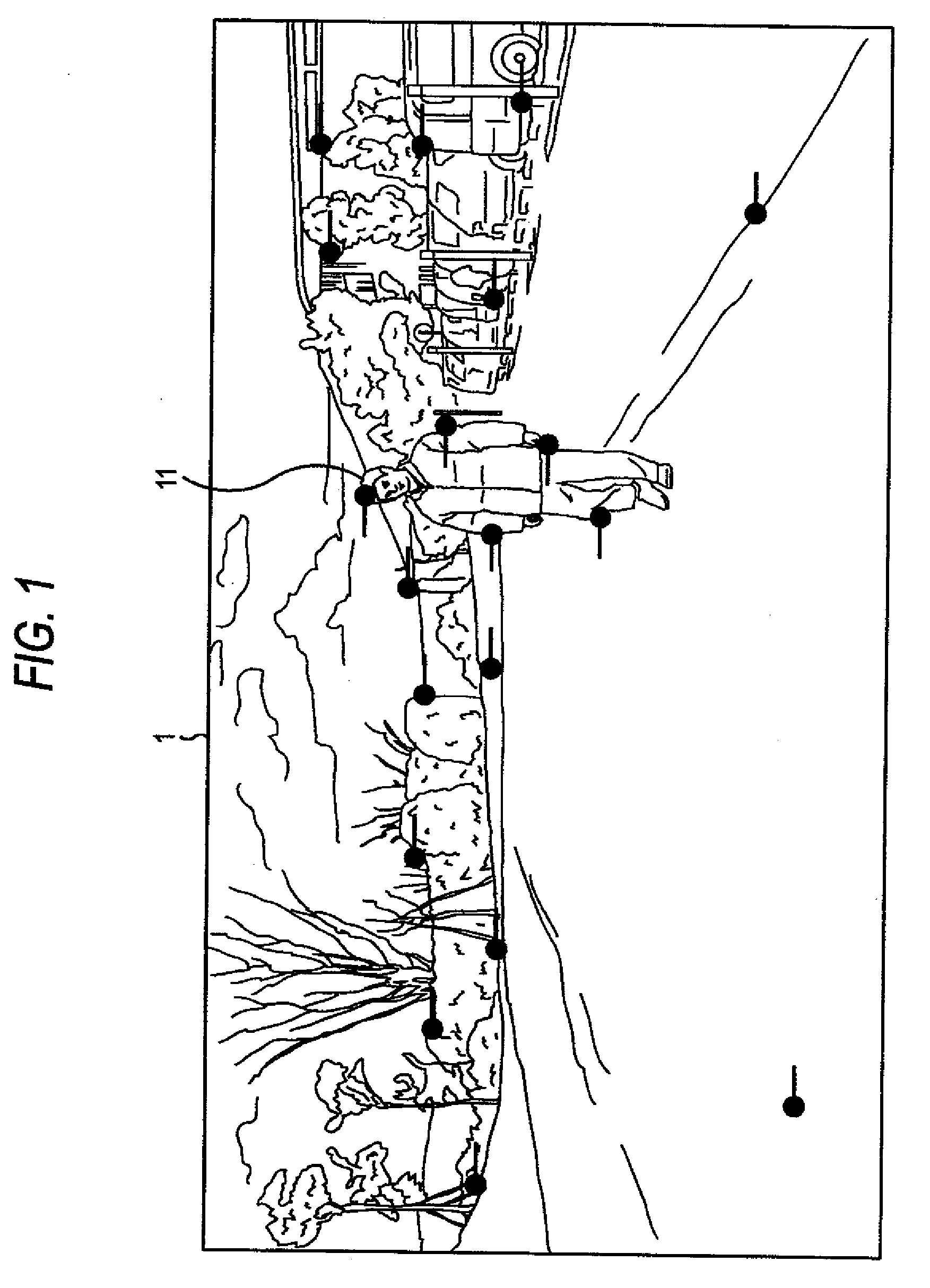
A rotational movement component of a camera provided on a mobile object is to be detected in a precise and simple manner. Three motion vectors extracted from the forward images captured by a camera mounted on a vehicle are extracted on a random basis. A temporary rotation angle is calculated using the extracted motion vectors based on a relational expression that represents the relationship between a background vector and the rotation angle of the camera, the relational expression being a linear expression of the yaw angle, pitch angle, and roll angle of the rotational movement of the camera. An error when using the temporary rotation angle is calculated for other motion vectors, and the number of motion vectors for which the error is within a predetermined threshold value is counted. After repeating such a process for a predetermined number of times, the temporary rotation angle with the largest number of motion vectors for which the error is within the predetermined threshold value is selected as the rotation angle of the camera. The present invention can be applied to an in-vehicle obstacle detecting device.

Description


Claims


Application Information

Patent Timeline
Owner ORMON CORP
Why Eureka
Try Eureka