Vibratory Dental Tool

a dental tool and vibration technology, applied in dental tools, mechanical energy handling, dental surgery, etc., can solve the problems of affecting the patient's oral health, so as to achieve the effect of convenient repositioning

Inactive Publication Date: 2008-12-25
DISCUS DENTAL LLC
View PDF4 Cites 20 Cited by
  • Summary
  • Abstract
  • Description
  • Claims
  • Application Information

AI Technical Summary

Benefits of technology

The technical effect of this patented technology is that it allows for easy adjustment of an implant by rotating its tip while keeping it still securely attached to the patient's teeth.

Problems solved by technology

The technical problem addressed in this patent is how to reduce the time it takes for dentists to manually scale teeth while also reducing stress and fatigue caused by the use of powered scaling tools like ultrasound and sonic scalers.

Method used


Image

  • Vibratory Dental Tool
  • Vibratory Dental Tool
  • Vibratory Dental Tool

Examples


Embodiment Construction

[0048]The detailed description set forth below is intended as a description of the presently exemplified device provided in accordance with aspects of the present invention and is not intended to represent the only forms in which the present invention may be practiced or utilized. It is to be understood, however, that the same or equivalent functions and components may be accomplished by different embodiments that are also intended to be encompassed within the spirit and scope of the invention.

[0049]Unless defined otherwise, all technical and scientific terms used herein have the same meaning as commonly understood to one of ordinary skill in the art to which this invention belongs. Although any methods, devices and materials similar or equivalent to those described herein can be used in the practice or testing of the invention, the exemplified methods, devices and materials are now described.

[0050]The vibration of most, if not all, powered scalers, does not closely resemble the motion


PUM


Abstract

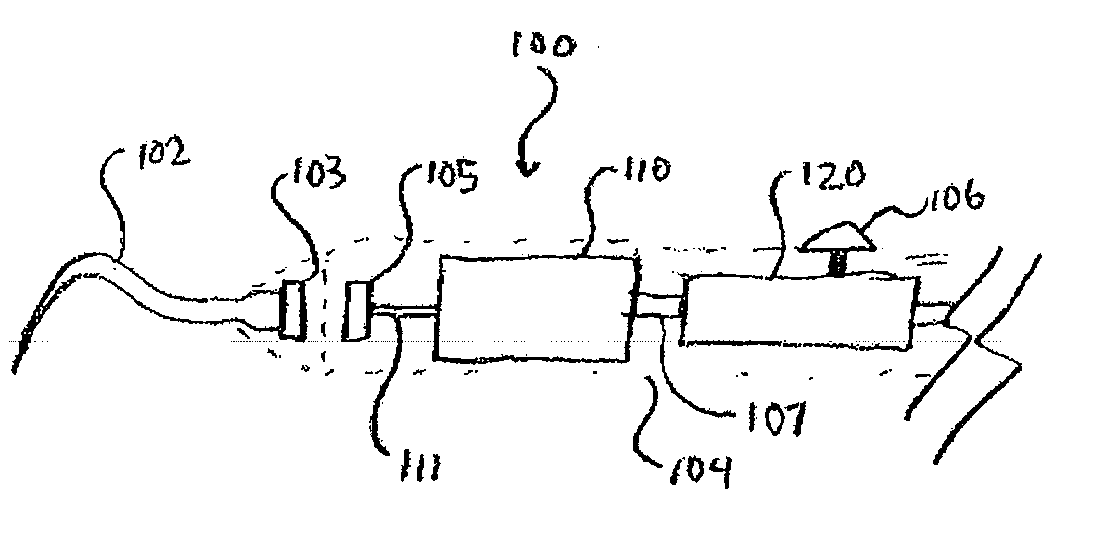
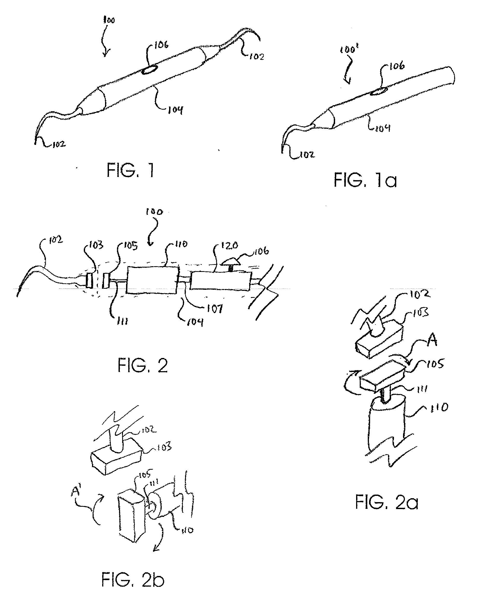
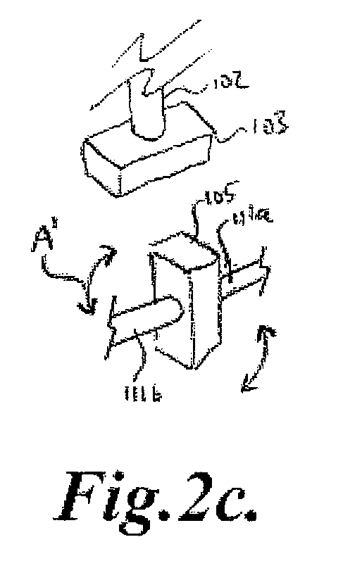
A powered dental tool generally includes a tool tip at its distal end, a body at its proximal end and a motion generating mechanism. In one aspect, the dental tool includes a tool tip having a proximal end and a distal end along a generally longitudinal axis and a reciprocating motion generating mechanism. The reciprocating motion generating mechanism may repeatedly move the tool tip generally back and forth by a given displacement generally along the tool tip's longitudinal axis. This displacement generally resembles the action of a hand scaler, i.e., a reciprocating motion along the longitudinal axis of the scaler, which is unlike the vibration of most powered scalers. Such action may be advantageous as it may be more intuitive for the dental professional or hygienist and may provide more effective scaling action. It may further be advantageous for a powered scaler to more closely resemble a hand scaler in form, which is small, portable and untethered. In one embodiment, the motion generating mechanism may include a rotational source and set of opposing magnetic transfer elements.

Description


Claims


Application Information

Patent Timeline
Owner DISCUS DENTAL LLC
Why Eureka
Try Eureka