Ignition coil

Inactive Publication Date: 2009-01-01
DENSO CORP
View PDF10 Cites 1 Cited by
  • Summary
  • Abstract
  • Description
  • Claims
  • Application Information

AI Technical Summary

Benefits of technology

[0009]The present invention addresses the above disadvantages. Thus, it is an objective of the present invention to provide an ignition coil having a ventilation passage that effectively prevents water or the like from entering into the coil using a simple structure.

Problems solved by technology

However, in the ignition coil in which the coil part is inserted in the connector case part, further devices are needed to prevent more effectively water or the like from entering into the plug hole using a simple structure.

Method used


Image

  • Ignition coil
  • Ignition coil
  • Ignition coil

Examples


Example

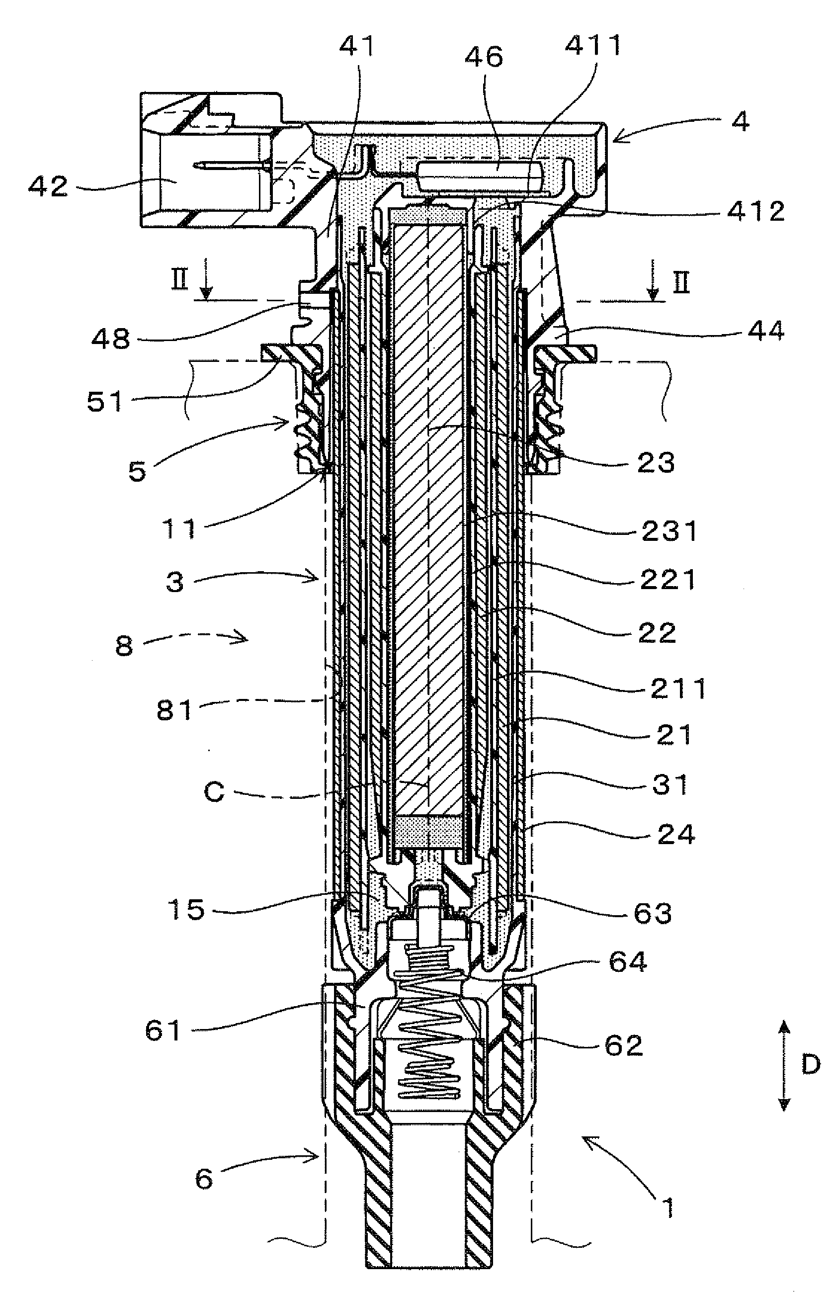
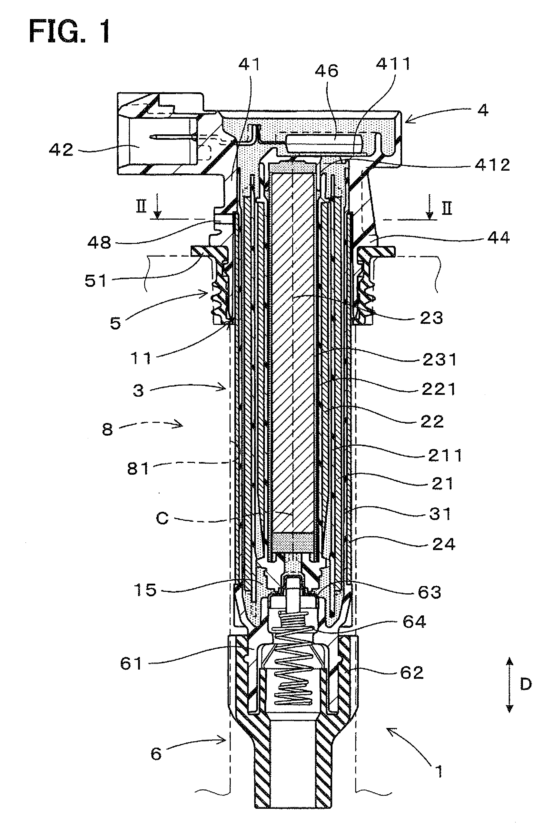
[0015]An embodiment of the invention is described below. In the invention, a projection that is in contact with an outer circumferential surface of a peripheral core is formed at two or more positions in a circumferential direction of the connector case part on an inner wall surface of an insertion hole of a connector case part. A ventilation clearance may be formed preferably between the inner wall surface of the insertion hole and the outer circumferential surfaces of the peripheral core. In such a case, the ventilation clearances are formed as evenly as possible in the circumferential direction to have as large passage cross-sectional areas as possible in the circumferential direction, using a clearance formed between the projections. Also, the outer circumferential surface of the peripheral core slides on surfaces of the projections, and thereby the peripheral core of a coil part is smoothly inserted into the insertion hole.

[0016]The peripheral core has a notch formed over an overa


PUM


Abstract

An ignition coil includes a coil part having primary and secondary coils, a center core, and a peripheral core, a connector case part, a seal rubber, and a ventilation passage. The coil part is inserted in a plug hole of an engine, and the case part is outside the plug hole. An axial end of the peripheral core is inserted in an insertion hole of the case part. The peripheral core and an inner wall surface of the insertion hole define a ventilation clearance therebetween. A gap between the case part and the plug hole is sealed with the rubber. The rubber is closely-attached to the plug hole and the case part along its whole circumference. The passage, through which the plug hole is ventilated, includes the clearance and a ventilation hole formed at a certain position of the case part away from the rubber to communicate with the clearance.

Description


Claims


Application Information

Patent Timeline
Owner DENSO CORP
Why Eureka
Try Eureka