Thrust washer for universal joint cross

a technology of universal joint and washer, which is applied in the direction of sliding contact bearings, couplings, mechanical equipment, etc., can solve the problems of premature wear and generation of undesirable noise and vibrations

Inactive Publication Date: 2009-01-08
DANA AUTOMOTIVE SYST GRP LLC
View PDF11 Cites 7 Cited by
  • Summary
  • Abstract
  • Description
  • Claims
  • Application Information

AI Technical Summary

Benefits of technology

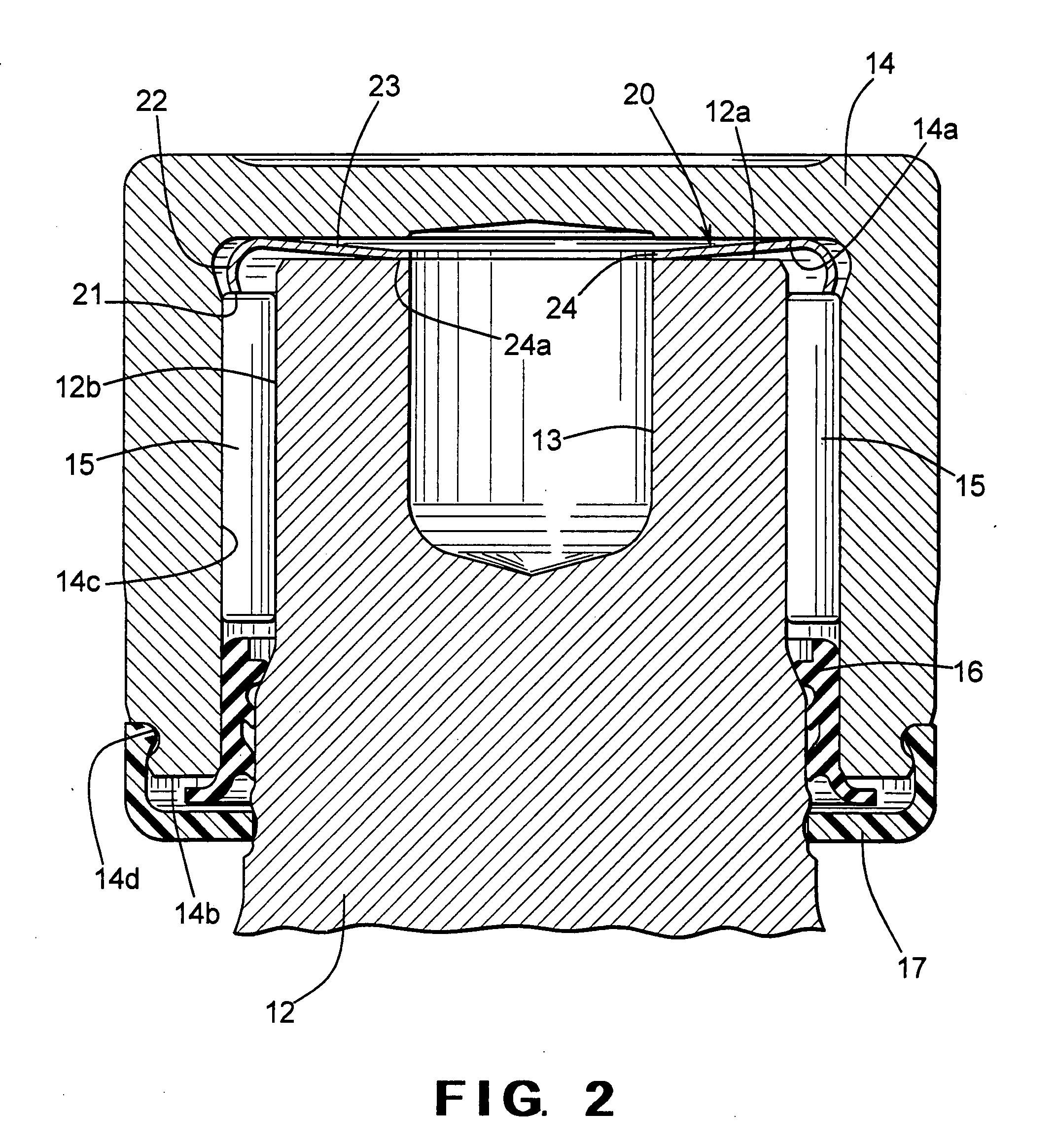
[0005]This invention relates to an improved structure for a thrust washer that is adapted to be disposed between a trunnion and a bearing cup of a universal joint cross. The cross includes a body including an outwardly extending trunnion and a bearing cup mounted on the trunnion. A thrust washer is disposed between the trunnion and the bearing cup. The thrust washer includes an outer edge portion, a spacer portion that extends from the outer edge portion and is curved in cross sectional shape, a spring portion that extends generally radially inwardly from the spacer portion and is shaped generally in the form of a hollow cone, and an inner lip portion that extends inwardly from the spring portion. The thrust washer absorbs thrust loads that occur between an outer end surface of the trunnion and an inner surface of a closed end of the bearing cup and takes up any axial looseness therebetween.

Problems solved by technology

If the end walls of the bearing cups fit tightly against the axially outer ends of the trunnions and bearings, friction between the surfaces during operation of the universal joint can generate heat and cause premature wear.
On the other hand, if the end walls of the bearing cups fit loosely on the trunnions, the cross can undesirably move relative to the bearing cups during operation of the universal joint, which can result in imbalances and generate undesirable noise and vibrations.

Method used


Image

  • Thrust washer for universal joint cross
  • Thrust washer for universal joint cross
  • Thrust washer for universal joint cross

Examples


Embodiment Construction

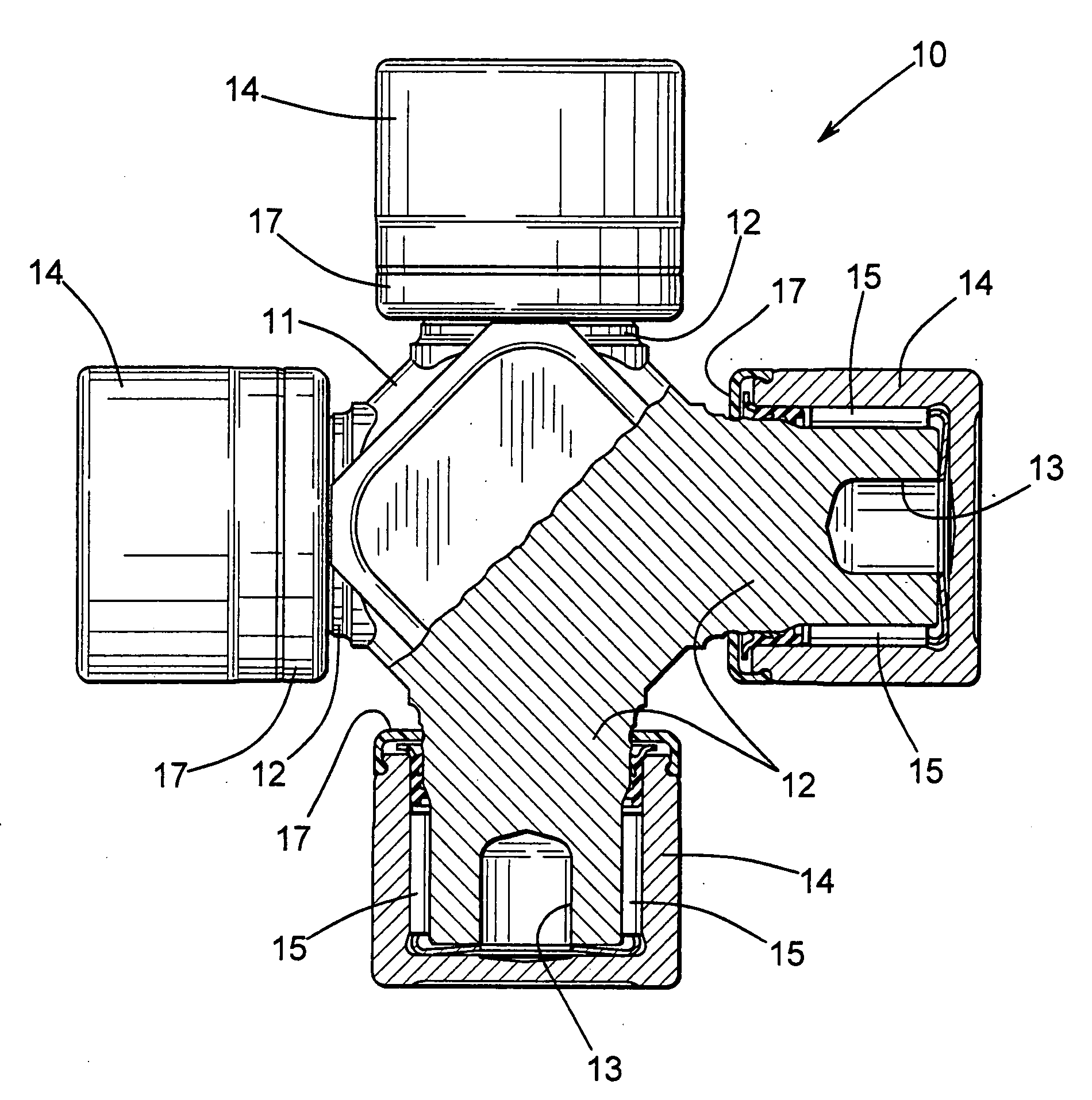
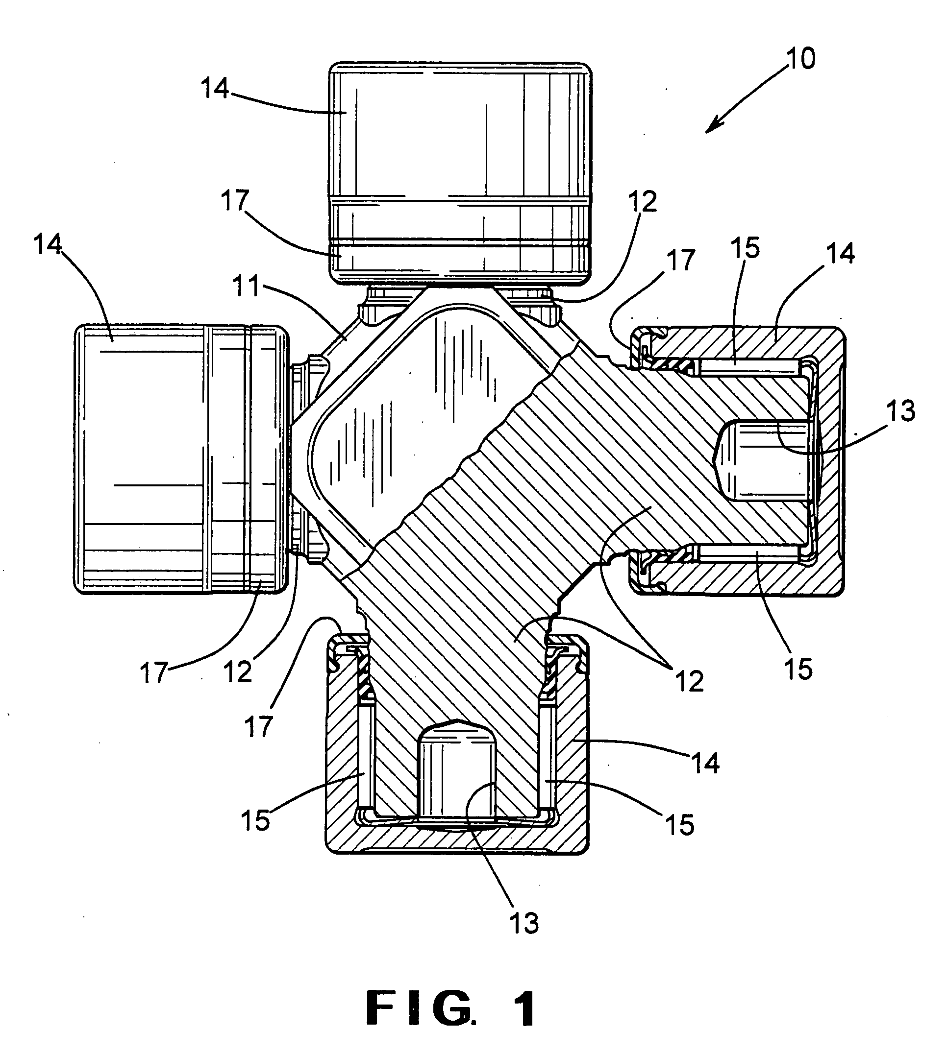
[0023]Referring now to the drawings, there is illustrated in FIG. 1 a cross, indicated generally at 10, in accordance with this invention. The cross 10 is adapted to form a portion of a universal joint (not shown), such as described above and conventionally used in drive train system. The illustrated cross 10 includes a central body 11 having a plurality of trunnions 12 extending outwardly from the body 11. In the illustrated embodiment, four of such trunnions 12 are formed integrally with the body 11. The illustrated trunnions 12 are disposed at right angles relative to one another and are oriented so as to lie in a single plane, although such is not required. The illustrated trunnions 12 are generally cylindrical in shape and define respective axes of rotation, although again such is not required.

[0024]As best shown in FIG. 2, each of the illustrated trunnions 12 is generally cylindrical in shape, having an outer end surface 12a and an outer cylindrical surface 12b. However, the t...


PUM


Abstract

A cross for a universal joint includes a body including an outwardly extending trunnion and a bearing cup mounted on the trunnion. A thrust washer is disposed between the trunnion and the bearing cup. The thrust washer includes an outer edge portion, a spacer portion that extends from the outer edge portion and is curved in cross sectional shape, a spring portion that extends generally radially inwardly from the spacer portion and is shaped generally in the form of a hollow cone, and an inner lip portion that extends inwardly from the spring portion. The thrust washer absorbs thrust loads that occur between an outer end surface of the trunnion and an inner surface of a closed end of the bearing cup and takes up any axial looseness therebetween.

Description

BACKGROUND OF THE INVENTION[0001]This invention relates in general to thrust washers that are disposed between the outer ends of trunnions and the inner surfaces of bearing cups in universal joint crosses. More specifically, this invention relates to an improved structure for such a thrust washer.[0002]Universal joints are well known devices that provide a driving connection between two members adapted to rotate about non-aligned axes of rotation. Universal joints are widely used between rotatable drive shaft sections in vehicle drive train systems. A typical universal joint includes a cross having a central body portion with four cylindrical trunnions extending outwardly therefrom. The trunnions are oriented in a single plane and extend at right angles relative to one another. A hollow cylindrical bearing cup having a cylindrical outside wall and a circular end wall is mounted on the end of each of the trunnions. A plurality of bearings, such as needle bearings or roller bearings, ...

Claims


Application Information

Patent Timeline
Patent Type & Authority Applications(United States)
IPC IPC(8): F16D3/40
CPCF16C17/08F16D3/41F16D3/385F16C21/005F16C2361/41
Inventor WANG, DAWHORNG D.
Owner DANA AUTOMOTIVE SYST GRP LLC
Why Eureka
Try Eureka