Liquid crystal display

a liquid crystal display and display technology, applied in static indicating devices, instruments, non-linear optics, etc., can solve the problems of reducing the gamma value of yellow colors, the limitation of reducing parasitic capacitance, etc., to reduce parasitic capacitance, increase aperture ratio, and reduce parasitic capacitance

Active Publication Date: 2009-02-05
SHENZHEN CHINA STAR OPTOELECTRONICS TECH CO LTD
View PDF5 Cites 8 Cited by
  • Summary
  • Abstract
  • Description
  • Claims
  • Application Information

AI Technical Summary

Benefits of technology

The technology described in this patented allows for better control over how much light can be transmitted through an LCD panel without leaking it or causing other issues such as signal interference caused by nearby wires that are connected with pixels at different locations within each screen area. This helps improve image quality while reducing power consumption.

Problems solved by technology

In conventional LCDs (Liquid Crystals Display), the use of multiple layers can cause issues like crossover current flow through certain areas called dark zones caused by insufficient overlap between different parts of the substrate's surface. Additionally, some manufacturing processes require high temperatures during production causing unwanted side effects such as shrinking of materials near specific points within the devices themselves. These limitations make these techniques difficult to achieve consistency across all screens without adding extra components.

Method used


Image

  • Liquid crystal display
  • Liquid crystal display
  • Liquid crystal display

Examples


Embodiment Construction

[0038]The advantages and characteristics of the present invention and means for achieving them will become apparent from the following detailed description of the exemplary embodiments and the accompanying drawings. However, the present invention is not limited by the hereafter disclosed exemplary embodiments, but may be modified in various different ways. The present exemplary embodiments provide complete disclosure of the present invention and complete information of the scope of the present invention to those skilled in the art, and the present invention is defined by the scope of the claims.

[0039]In the drawings, the thickness of layers, films, panels, regions, etc., are exaggerated for clarity, and like reference numerals designate like elements throughout the specification.

[0040]It will be understood that when an element such as a layer, film, region, or substrate is referred to as being “on” another element, it can be directly on the other element or intervening elements may als


PUM


Abstract

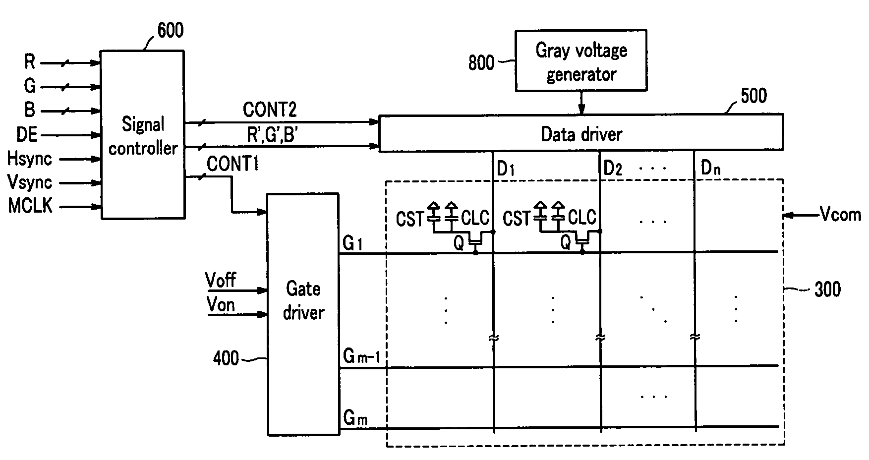
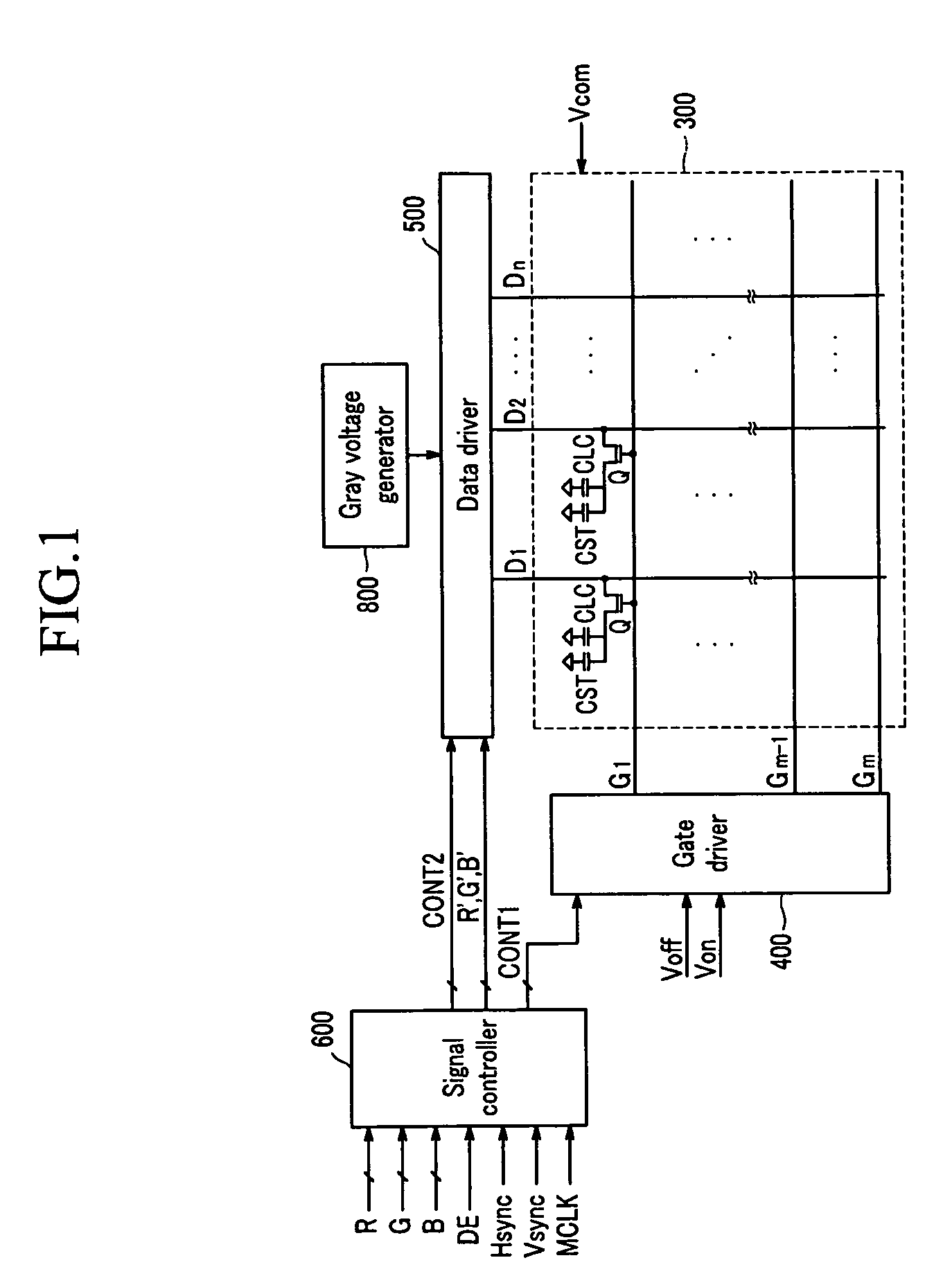
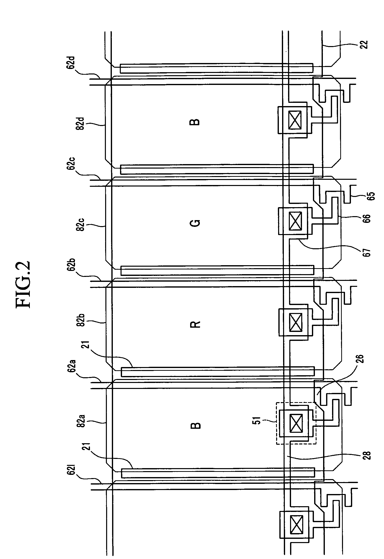
A liquid crystal display to prevent light leakage with an improvement of aperture ratio and a reduction of load of a data line is provided. The liquid crystal display includes a gate line and a storage electrode line formed on a insulating substrate and apart from each other, a first data line and a second data line intersecting the gate line, a first pixel electrode defined by the gate line and the first data line, and a second pixel electrode defined by the gate line and the second data line and neighboring the first pixel electrode. Also, a blocking electrode between the first pixel electrode and the second pixel electrode is included, wherein at least portion of the first data line is disposed under the first pixel electrode, and at least portion of the blocking electrode is disposed under the second pixel electrode and apart from the first data line.

Description


Claims


Application Information

Patent Timeline
Owner SHENZHEN CHINA STAR OPTOELECTRONICS TECH CO LTD
Why Eureka
Try Eureka