Suspended gun rest

a gun rest and suspension technology, applied in the direction of suspension devices, machine supports, wearable arms, etc., can solve the problems of limiting the range of motion, limiting the accuracy of sighting a moving target and keeping one's aim, and not allowing a hunter to properly track a moving targ

Active Publication Date: 2009-03-12
SAUNDERS III JAMES W
View PDF35 Cites 11 Cited by
  • Summary
  • Abstract
  • Description
  • Claims
  • Application Information

AI Technical Summary

Benefits of technology

This patent describes an improved way for people who want to use their guns while they are still on stage or at home. They have a special purpose gun stand with a lock mechanism that makes it easy to change positions when needed. It also has a mounting device that lets them easily rotate around a supporting structure like a pole. Users don't need to leave the gun behind if they just hit something again.

Problems solved by technology

The technical problem addressed by this patent is how to create a gun stand with a secure and easy-to-use feature that allows the user to move their weapon without being limited by the ground conditions they are facing.

Method used


Image

  • Suspended gun rest
  • Suspended gun rest
  • Suspended gun rest

Examples


Embodiment Construction

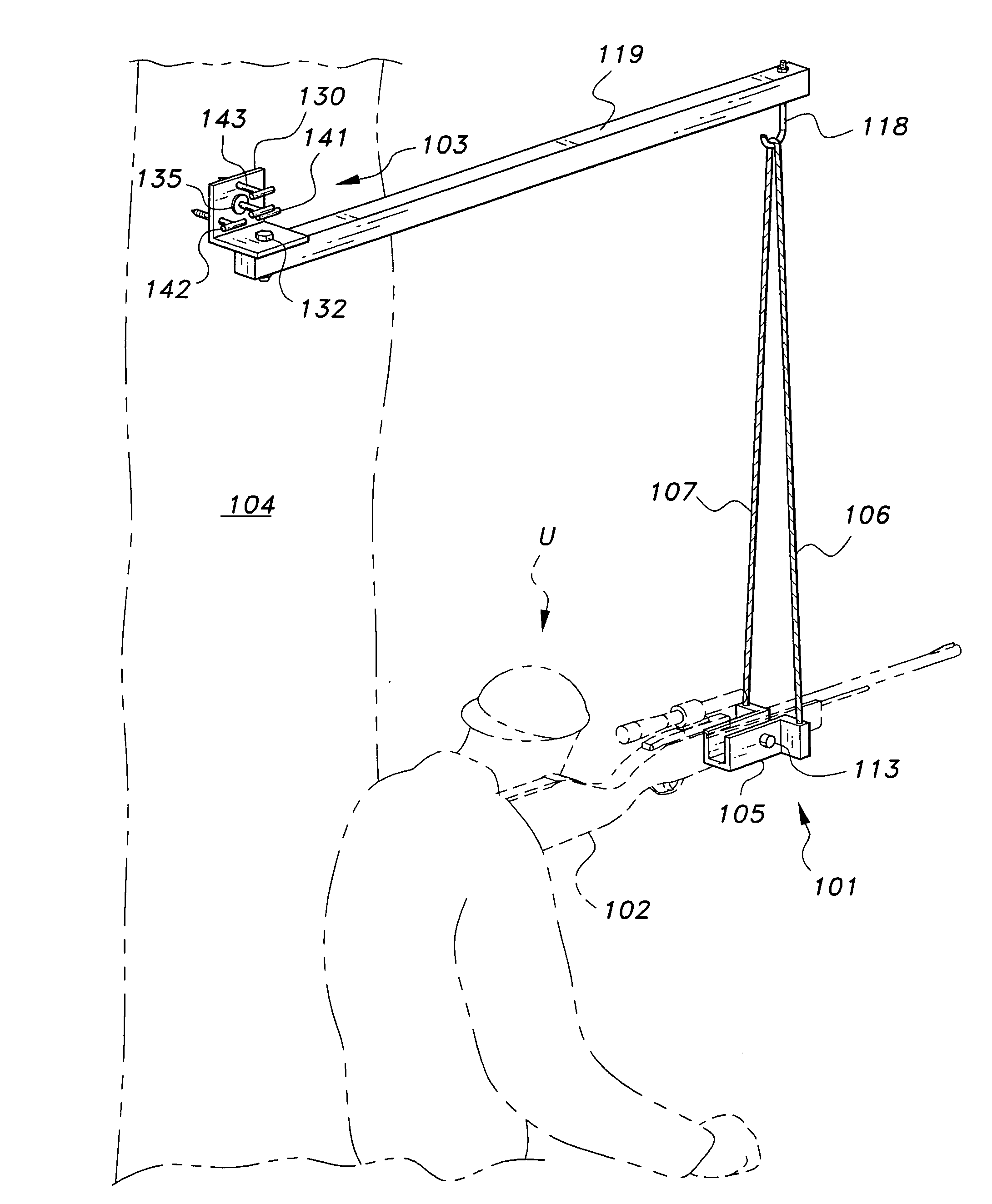
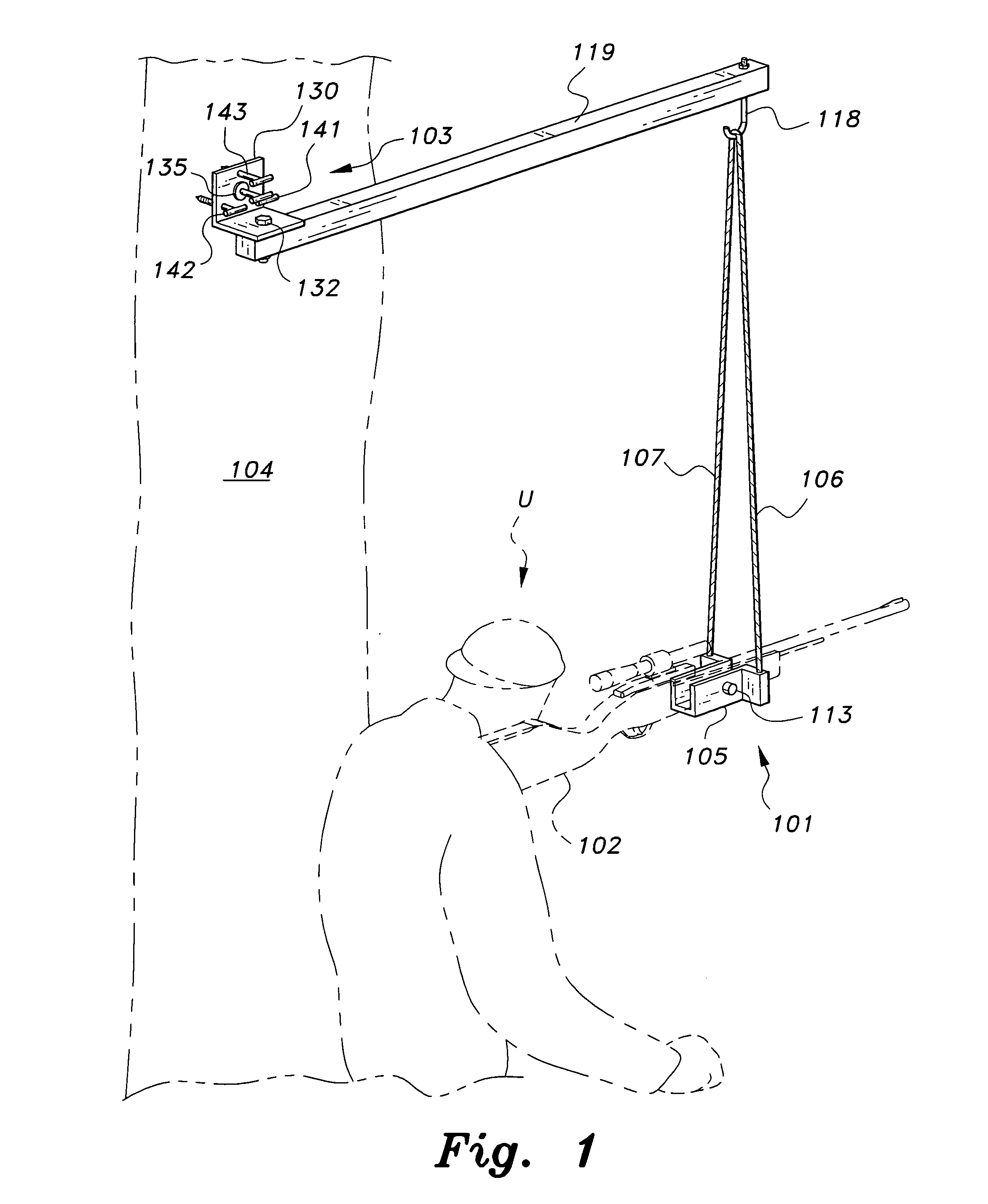
[0029]The present invention is directed towards a suspended gun rest 101. As shown in FIG. 1, the suspended gun rest 101 supports a firearm 102 and has a mount 103 with a pivoting arm 119 that is attached to a rigid support 104 (such as the exemplary tree shown in FIG. 1). The rest 101 includes a cradle 105, a pair of strings or lines 106, 107, a string routing system 116, 117 and 120 (to be described in greater detail below, with regard to FIGS. 3 and 4), a locking mechanism 121 (preferably including a pivoting lever 109, best shown in FIGS. 3 and 4), and a spindle 110. The string or line may be formed from regular string, cable and / or chain, or any other suitable material.

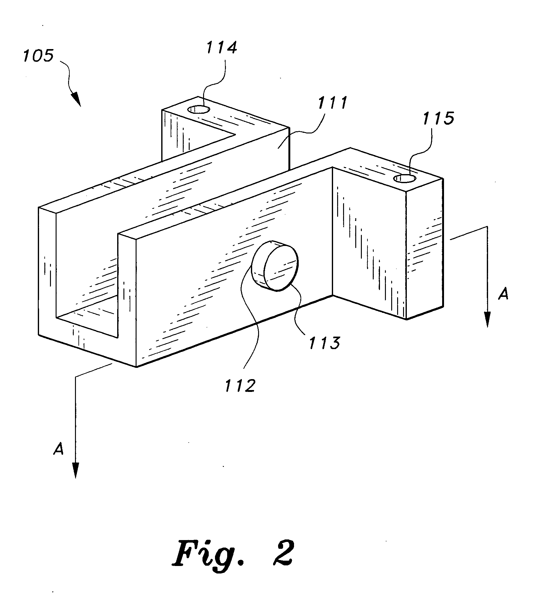
[0030]FIG. 2 shows the cradle 105 having an opened slot 111 formed therethrough to receive the firearm. The cradle 105 has a guide hole 112 on the side for a button 113 to move in and out of the cradle 105. The top of the cradle 105 has two holes 114, 115 formed therethrough for the two strings 106, 107 to pass in


PUM


Abstract

The suspended gun rest includes a pivoting arm adjustably mounted to a rigid support by a mount. The mount comprises an L-shaped bracket with a mounting hole and three holes for adjustment screws. A cradle is provided which includes two strings, a string routing system, a locking mechanism and a spindle. A hook is connected to one end of the pivoting arm. The two strings are connected to the spindle and routed through the cradle by the routing system and attached to the hook on the pivoting arm.

Description


Claims


Application Information

Patent Timeline
Owner SAUNDERS III JAMES W
Why Eureka
Try Eureka