Ball head joint finger mechanism with flexible connection and hydraulic drive

A technology of flexible connection and ball joints, applied in the direction of joints, chucks, manipulators, etc., can solve the problems of excessive finger joint structure, finger joint flexibility and driving force, etc., and achieve the effect of flexible movement, compact structure and large driving force

Active Publication Date: 2019-11-22
SOUTHEAST UNIV
View PDF10 Cites 2 Cited by
  • Summary
  • Abstract
  • Description
  • Claims
  • Application Information

AI Technical Summary

Benefits of technology

This new design allows for better movement by allowing balls that rotate or move freely without being damaged when they are connected together. It also provides greater power than previous designs due to its use of fluid pressure instead of pneumatic cylinders. Additionally, this system uses soft connections between different parts rather than hard ones like welding them together, resulting in less wear on components overall.

Problems solved by technology

This patents discusses different ways how robots use their own parts like hands instead of relying on external power sources such as batteries. However, current designs have issues related to flexibility, complexity, space requirements, durability, etc., making them challenging to achieve high performance levels without sacrificing functionality during extreme environments where shock forces may occur.

Method used


Image

  • Ball head joint finger mechanism with flexible connection and hydraulic drive
  • Ball head joint finger mechanism with flexible connection and hydraulic drive
  • Ball head joint finger mechanism with flexible connection and hydraulic drive

Examples


Embodiment Construction

[0032] The technical solutions of the present invention will be described in detail below in conjunction with the accompanying drawings.

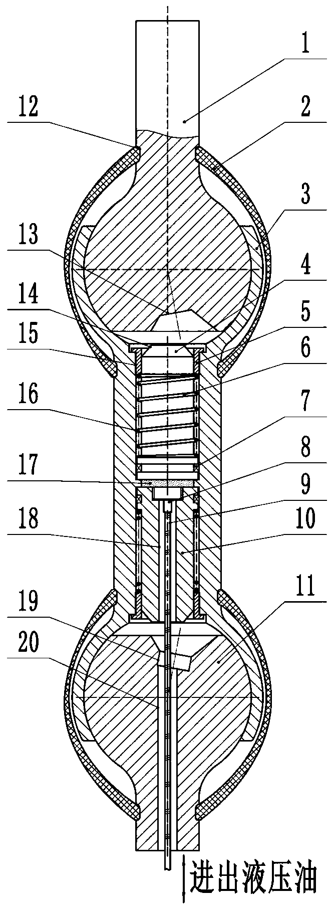
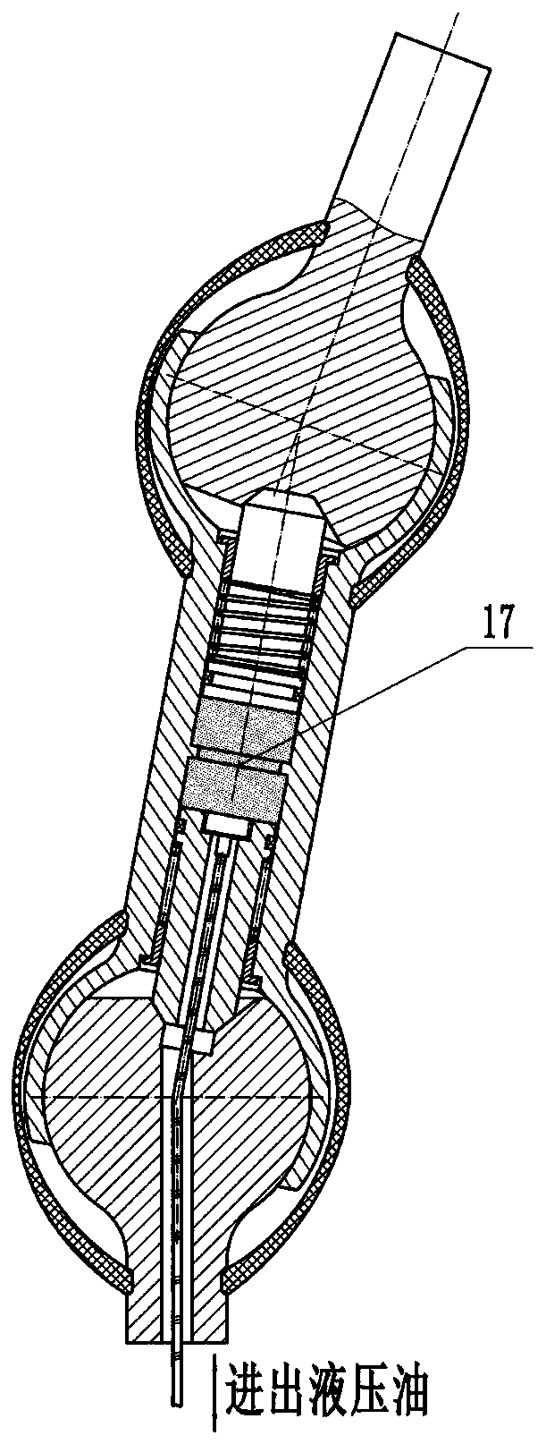
[0033] like Figures 1 to 5 As shown, the flexible connection and hydraulically driven ball joint finger mechanism of the present invention includes: a three-bar two-joint mechanism, a hydraulically driven locking mechanism, and a flexible connection mechanism; wherein:

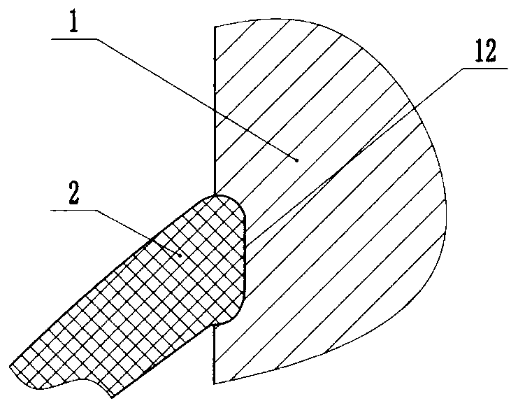
[0034] The three-bar two-joint mechanism includes two ball ends (upper ball head 1, lower ball head 11) and a ball socket 3 between the two ball ends. The two ball ends are respectively The first ball head, the second ball head;

[0035] Both the first ball head and the second ball head are rods with a ball head at one end, and the ball end of the first ball head and the ball end of the second ball head are both provided with a tapered groove 13 At the same time, the second ball head is provided with a ball head through hole 20, one end of the ball head through hole communi


PUM


Abstract

The invention provides a ball head joint finger mechanism with flexible connection and hydraulic drive. The ball head joint finger mechanism includes a three-rod two-joint mechanism, a hydraulically driven locking mechanism and a flexible connection mechanism; the three-rod two-joint mechanism includes a first ball head rod, a second ball head rod and a ball socket rod; a ball socket A and a ballsocket B are separately disposed at the two ends of the ball socket rod; the ball socket rod is provided with a ball socket rod through hole along the axis; the flexible connection mechanism includesa first flexible connecting piece and a second flexible connecting piece; the ball head end of the first ball head rod can be matched with the ball socket A and the ball head end of the first ball head rod and the ball socket A are connected through the first flexible connecting piece to form a first ball joint, and the ball head end of the second ball head rod can be matched with the ball socketB and the ball head end of the second ball head rod and the ball socket B are connected through the second flexible connecting piece to form a second ball joint; and the hydraulically driven locking mechanism is disposed in the ball socket rod through hole, and includes a first piston, a second piston and an oil chamber formed between the first piston and the second piston. The ball head joint finger mechanism has the characteristics of combining flexibility and rigidity, the structure is compact, the output force is larger than that under the condition of volume, the action is flexible, and manufacturability is high.

Description


Claims


Application Information

Patent Timeline
Owner SOUTHEAST UNIV
Why Eureka
Try Eureka