Device, Method and Vessel Assembly for the Measurement of Heat Flow at Least One Sample

a technology of heat flow and sample, applied in the direction of thermometers, instruments, material thermal analysis, etc., can solve the problems of long time period for equilibration and difficult temperature stability, and achieve the effect of fast measurement and controlled and stable measurement environmen

Active Publication Date: 2009-04-09
SYMCEL SVERIGE
View PDF8 Cites 12 Cited by
  • Summary
  • Abstract
  • Description
  • Claims
  • Application Information

AI Technical Summary

Benefits of technology

This patented technology allows for precise control over temperature during multiple parallel experiments involving different fluids. It can be used with various types of equipment such as reactors, pipes, and tanks. By controlling this temperature, researchers can study how well these materials behave under specific conditions.

Problems solved by technology

The technical problem addressed in this patent is how to provide a calorimetric instrument that can be easily handled and highly sensitive, allowing for accurate measurement of heat content in various fields without compromising their safety and reliability requirements.

Method used


Image

  • Device, Method and Vessel Assembly for the Measurement of Heat Flow at Least One Sample
  • Device, Method and Vessel Assembly for the Measurement of Heat Flow at Least One Sample
  • Device, Method and Vessel Assembly for the Measurement of Heat Flow at Least One Sample

Examples


Embodiment Construction

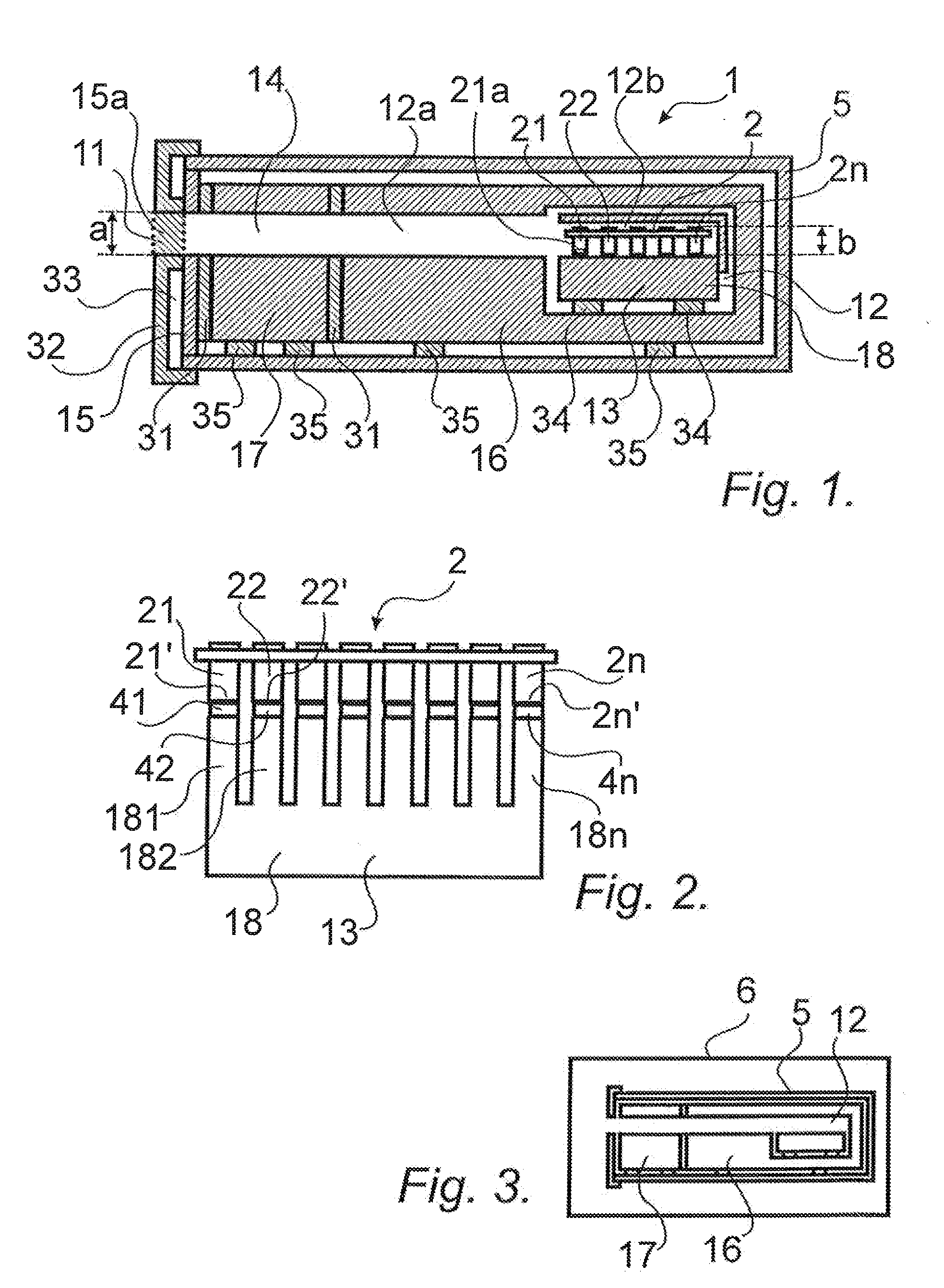
[0041]The present invention will now be described in more detail and with reference to FIG. 1, where a device 1 for the measurement of heat flow from at least one sample 21a is shown, the device 1 being adapted to receive a multi well vessel assembly 2 with samples in one or several vessels 21, 22, . . . , 2n.

[0042]The device 1 comprises an opening 11 for insertion of the vessel assembly 2 into the device 1, a measurement chamber 12 with a heat sink 13, a channel 14 extending from the opening 11 to the measurement chamber 12, a lid 15 for closing the opening during measurements, and a closing member 15a schematically shown in dotted lines in the figure.

[0043]The present invention specifically teaches that the opening 11 and channel 14 leads horizontally into the device 1, thus making it possible to have a relatively small opening 11 into the device 1. It is desirable to have the opening 11 as small as possible and the present invention teaches that the height “a” of the opening 11, th


PUM


Abstract

The present invention relates to a device and a method for the measurement of heat flow from at least one sample. The device 1 is adapted to receive a multi well vessel assembly (2) with samples in one or several vessels (21, 22, . . . 2n). The device (1) comprises an opening (11) for insertion of the vessel assembly (2) into the device (1), a measurement chamber (12) with a heat sink (13), a channel (14) extending from the opening (11) to the measurement chamber (12). The present invention specifically teaches that the opening (11) and channel (14) leads horizontally into the device (1), and that the height of the opening (11), channel (14) and measurement chamber (12) is only high enough to receive the vessel assembly (2).

Description


Claims


Application Information

Patent Timeline
Owner SYMCEL SVERIGE
Why Eureka
Try Eureka