Lens module
- Summary
- Abstract
- Description
- Claims
- Application Information
AI Technical Summary
Problems solved by technology
Method used
Image

Examples
first embodiment
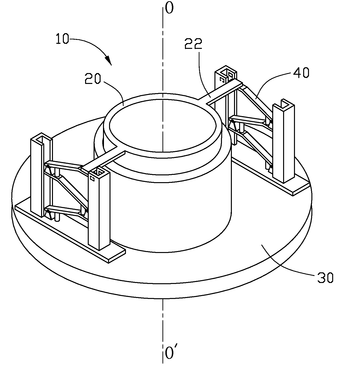
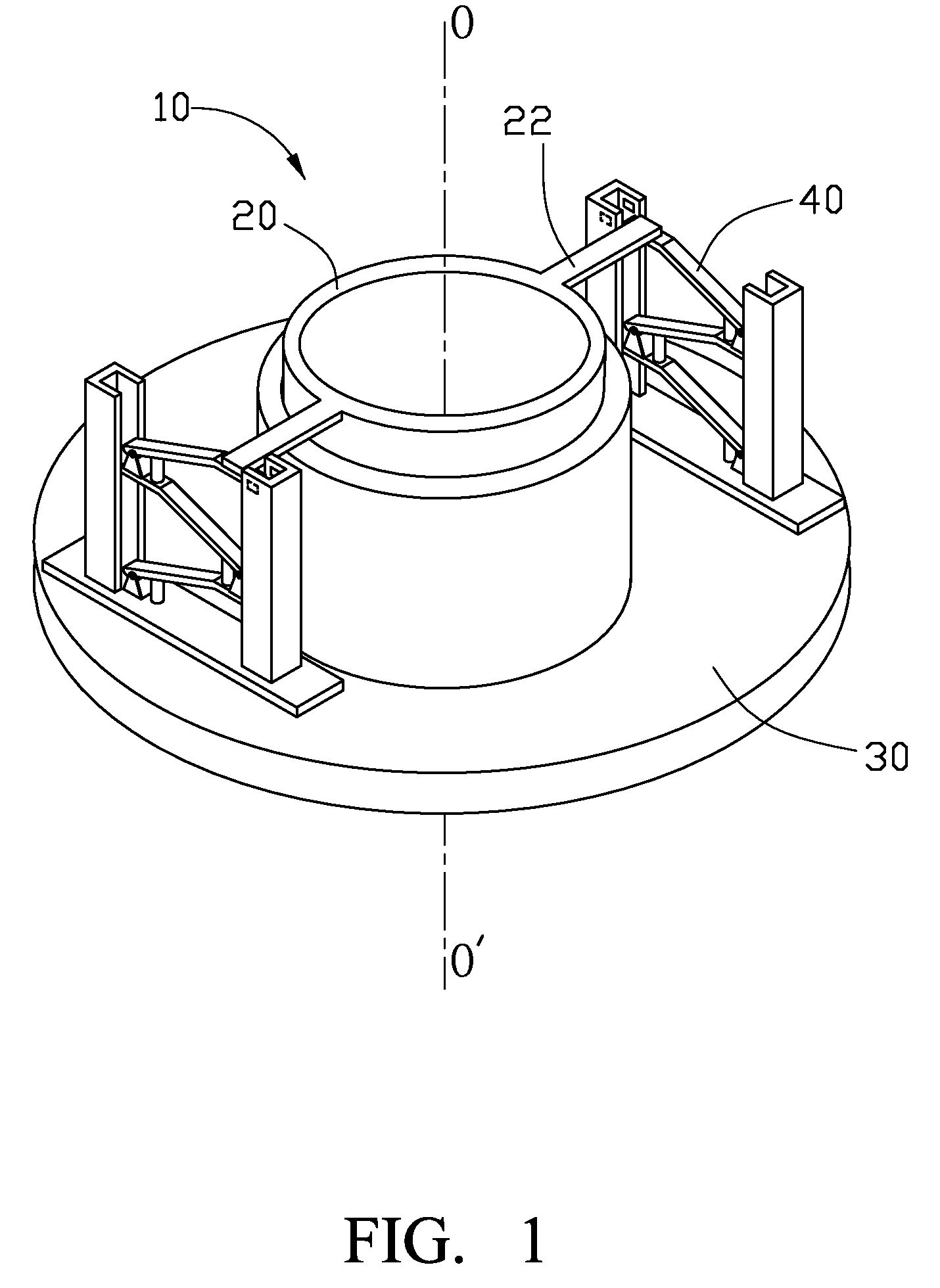
[0015]Referring to FIG. 1, a lens module 10 in accordance with the present disclosure includes a barrel 20, a holder 30, and two driving mechanisms 40 for the barrel 20.
[0016]The barrel 20 receives at least one lens 21 fixed to the inner surface by adhesive. The lens 21 has an optical axis OO′. An outer surface of the barrel 20 is smooth. Two connecting arms 22 extend horizontally from a top end of the barrel 20.
[0017]The holder 30 includes a receiving chamber 301 receiving the barrel 20 therein. A surface of the receiving chamber 301 is smooth. The barrel 20 moves along the optical axis OO′ of the lens 21 toward the holder 30.
[0018]Referring to FIG. 3, the driving mechanism 40 includes a first lever 41a, a second lever 41b, a third lever 41c, a first support 42a, a second support 42b, a third support 42c, a bottom plate 43, a first piezoelectric device 44a, a second piezoelectric device 44b, and a first piezoelectric device 44c.
[0019]Lever 41a includes a fixed end 411a, a moving end
second embodiment
[0024]Referring to FIGS. 4 and 5, an exemplary lens module 10a in accordance with the disclosure includes a barrel 20a, a holder 30a, two driving mechanisms 40a and a supporting member 50 supporting the two driving mechanisms 40a.
[0025]The barrel 20a and the holder 30a are both cylindrical. The lens barrel 20a has an outer thread 201 formed thereon. The holder 30a has an inner thread 302 formed therein. The lens barrel 20a is threaded with the holder 30a. A lens assembly 202 is received in the barrel 20a. The lens assembly 202 has an optical axis AO′. The lens assembly 202 includes a first retaining ring 203 receiving a first lens 2021 and a second retaining ring 204 receiving a second lens 2022.
[0026]Two connecting arms 2031 horizontally extend from the first retaining ring 203 respectively. The two connecting arms 2031 are fixed to the two driving mechanisms 40a respectively. The two driving mechanisms 40a move the barrel 20a along the optical axis AO′ in the holder 30a. Two connect
third embodiment
[0028]Referring to FIG. 6, an exemplary driving mechanism 40b of the lens module (not shown) in accordance with a third embodiment is provided, differing from driving mechanism 40 only in that driving mechanism 40b includes a first lever 410, a first support 420, a first piezoelectric device 440 and a bottom plate 430b. The first support 420 is mounted on the bottom plate 430b. The first lever 410 is pivotedly mounted on the first support 420. The first piezoelectric device 440 is arranged between the bottom plate 430b and the first lever 410.
PUM
 Abstract
Description
Claims
Application Information
 - R&D Engineer
- R&D Manager
- IP Professional
- Industry Leading Data Capabilities
- Powerful AI technology
- Patent DNA Extraction
Browse by: Latest US Patents, China's latest patents, Technical Efficacy Thesaurus, Application Domain, Technology Topic.
© 2024 PatSnap. All rights reserved.Legal|Privacy policy|Modern Slavery Act Transparency Statement|Sitemap