Measurement system with optical referencing

Active Publication Date: 2009-12-10
ROCHE DIABETES CARE INC
View PDF7 Cites 4 Cited by
  • Summary
  • Abstract
  • Description
  • Claims
  • Application Information

AI Technical Summary

Benefits of technology

[0024]In this manner the structure of the reference area and its behavior towards the analyte can be designed to be very similar to the reaction area. However, no optical absorption change due to the analyte occurs in the reference area. The first three variants can ensure that the properties of the sample are taken into consideration in the referencing which increases the accuracy of the measurement results. They can be used in

Problems solved by technology

The disadvantage of this method is that the background signal for referencing is not wetted by the sample and therefore has other optical properties than the area wetted with sample.
A disadvantage of this analytical system is

Method used


Image

  • Measurement system with optical referencing
  • Measurement system with optical referencing
  • Measurement system with optical referencing

Examples


Embodiment Construction

[0035]The following descriptions of the embodiments are merely exemplary in nature and are in no way intended to limit the present invention or its application or uses.

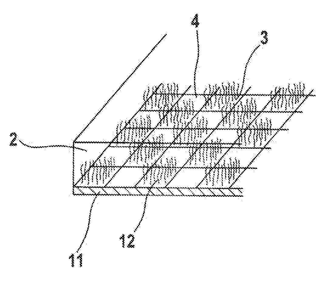
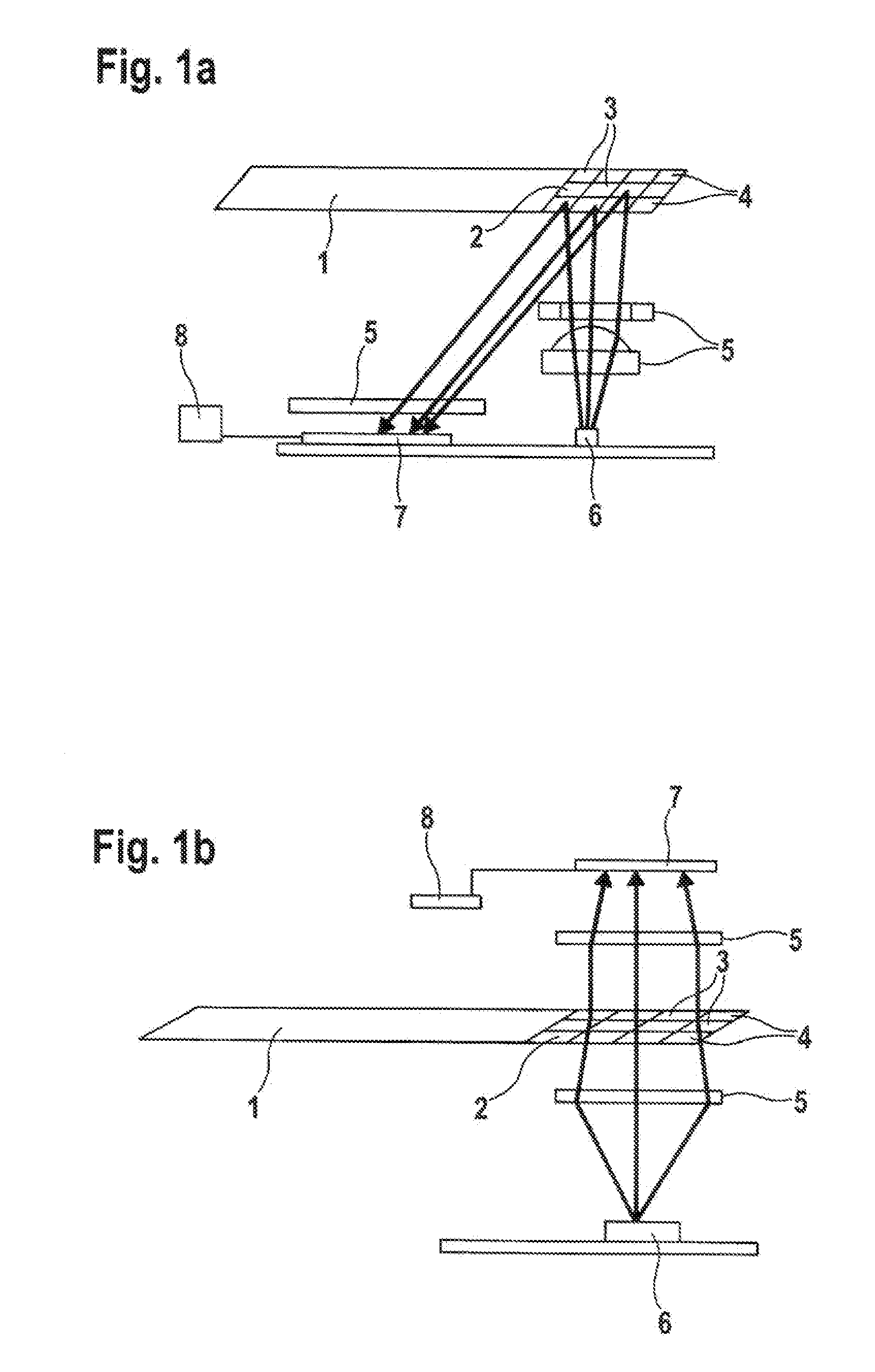
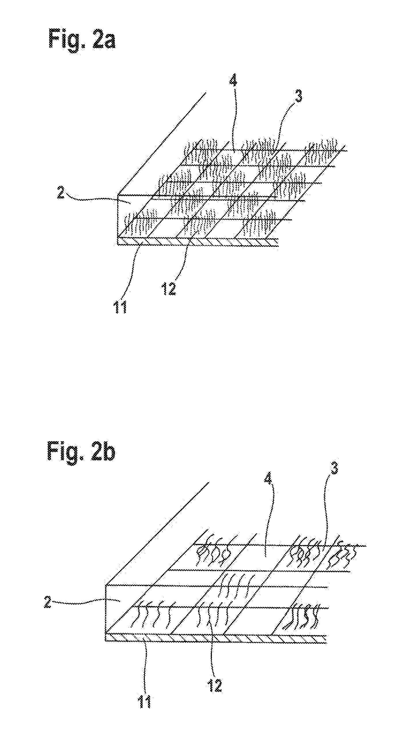
[0036]Embodiments of systems according to the present invention are shown in FIGS. 1a and 1b which show a test element (1) with a detection area (2) which contains several reference areas (4) and reaction areas (3). This system is only shown as an example with several reference areas and reaction areas; systems are also conceivable which only contain one reference area (4) and one reaction area (3).

[0037]In FIG. 1a the test element (1) is arranged in the system in such a manner that the detection area (2) is irradiated at least partially by an illumination unit (6) and the light reflected from the detection area (2) is captured by a detector (7). The signals received by the detector (7) can be processed further and evaluated in an evaluation unit (8). In one embodiment, the illumination or detection is spatially resolved


PUM


Abstract

A system is described for determining the concentration of an analyte in a liquid by absorption measurement comprising a test element with a detection area which contains at least one reaction area with reagents for detecting the analyte which cause a change in the absorption behavior upon reaction with the analyte. The detection area contains at least one reference area in which the absorption behavior is substantially not changed when wetted by a sample having the analyte. Furthermore, the system contains a detection unit for the spatially resolved detection of light intensities which are received from the detection area and an evaluation unit for evaluating signals from the detection unit. Further embodiments of the system comprise reaction areas and reference areas arranged alternately in two dimensions.

Description


Claims


Application Information

Patent Timeline
Owner ROCHE DIABETES CARE INC
Why Eureka
Try Eureka