Compliant expansion swage

Active Publication Date: 2010-04-15
WEATHERFORD TECH HLDG LLC
View PDF68 Cites 11 Cited by
  • Summary
  • Abstract
  • Description
  • Claims
  • Application Information

AI Technical Summary

Problems solved by technology

However, the fixed diameter cone provides no flexibility in the radially inward direction to allow for variations in the internal diameter of the casing.
This variation in the internal diameter of the casing can cause the fixed diameter cone to become stuck in the wellbore, if the variation is on the low side.
A stuck fixed diameter cone creates a major, time consuming and costly problem that can necessitate a sidetrack of the wellbore since the solid cone cannot be retrieved from the well and the cone is too hard to mill up.
Further, this variation in the internal diameter of the casing can also cause an inadequate expansion of the tubular in the casing if the variation is on the high side, which may result in an inadequate coupling between the tubular and the casing.

Method used


Image

  • Compliant expansion swage
  • Compliant expansion swage
  • Compliant expansion swage

Examples


Example

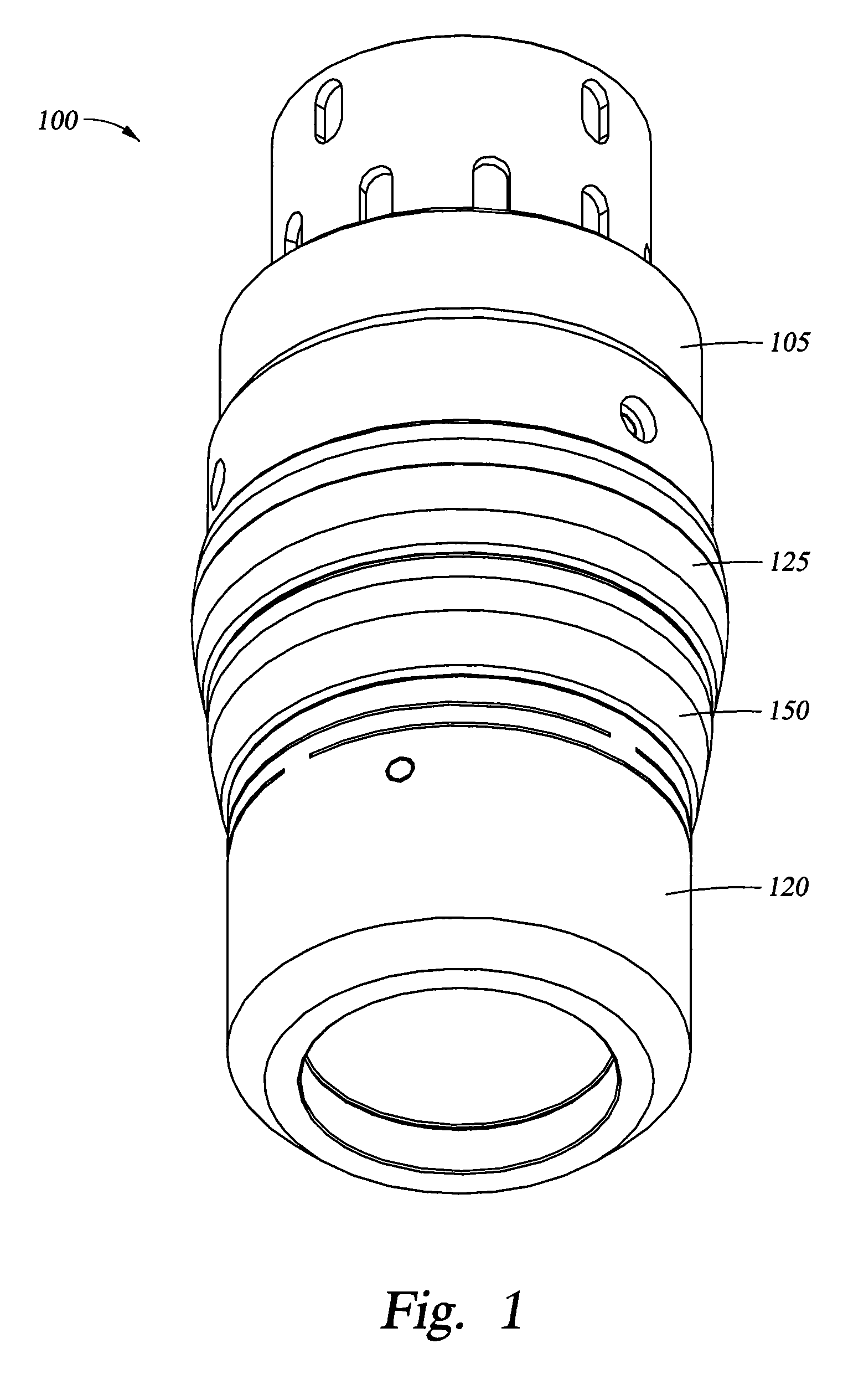
[0032]Embodiments of the invention generally relate to a swage assembly having a cone portion capable of deflecting in response to a restriction or obstruction encountered while expanding a tubular. While in the following description the tubular is illustrated as a liner, the tubular can be any type of downhole tubular. For example, the tubular may be an open-hole patch, a cased-hole patch or an expandable sand screen. To better understand the aspects of the swage assembly of the present invention and the methods of use thereof, reference is hereafter made to the accompanying drawings.

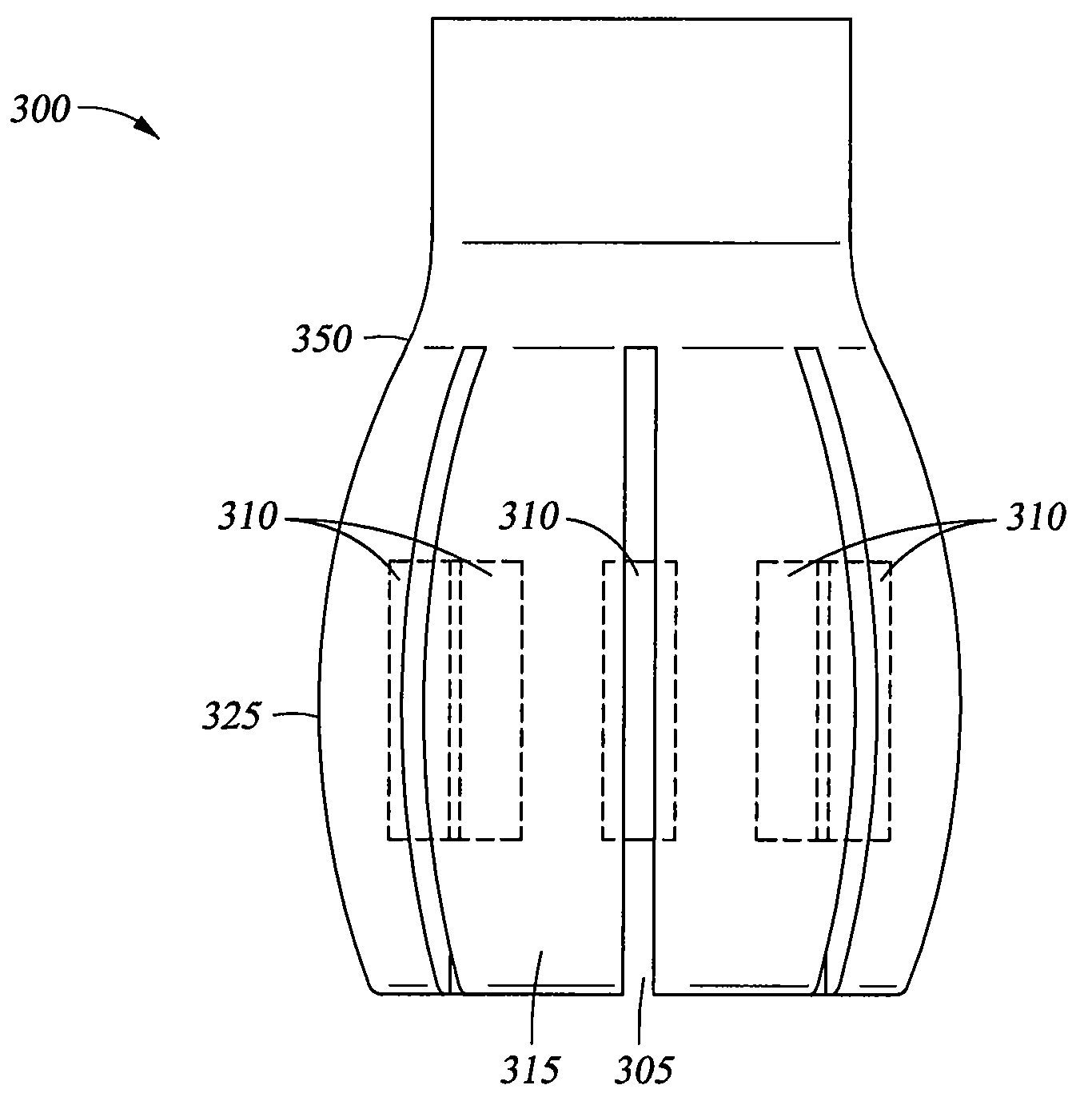
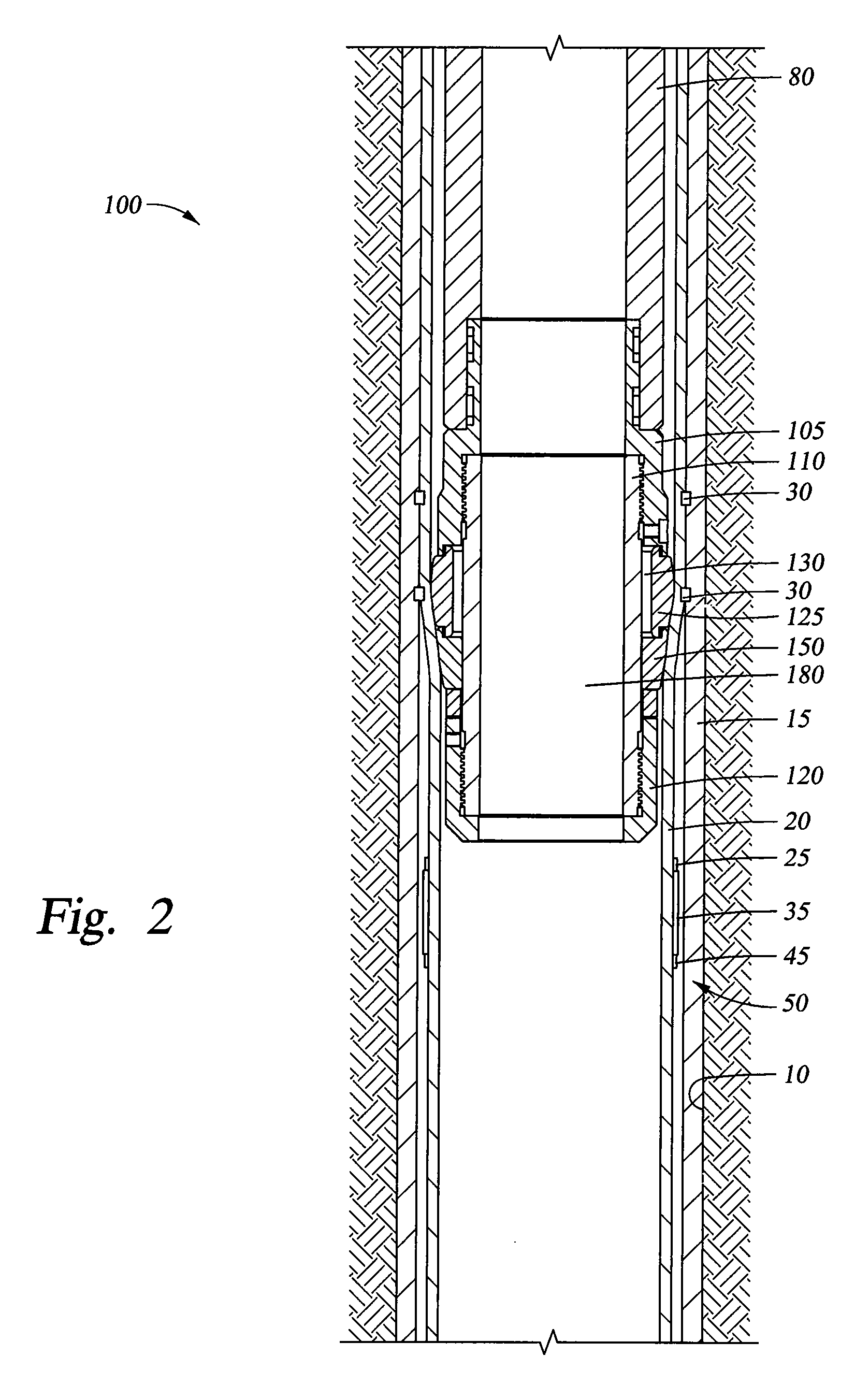
[0033]FIG. 1 is an isometric view of a swage assembly 100 according to one embodiment of the invention. The swage assembly 100 is configured to expand a tubular in the wellbore. The swage assembly 100 generally includes a substantially solid deformable cone 125. As will be described herein, the swage assembly 100 may be moved from a first configuration where the swage assembly 100 has a substantially comp


PUM

PropertyMeasurementUnit
Pressureaaaaaaaaaa
Diameteraaaaaaaaaa
Deformation enthalpyaaaaaaaaaa

Abstract

The present invention generally relates to a swage assembly that is movable from a compliant configuration having a first shape to a substantially non-compliant configuration having a second shape. In one aspect, an expansion swage for expanding a wellbore tubular is provided. The expansion swage includes a body and a solid cone disposed on the body. The expansion swage further includes a deformable cone disposed on the body, wherein the solid cone is made from a first material and the deformable cone is made from a second material and wherein the deformable cone is movable relative to the body when the expansion swage is in a compliant configuration. In another aspect, a method of expanding a wellbore tubular is provided.

Description


Claims


Application Information

Patent Timeline
Owner WEATHERFORD TECH HLDG LLC
Why Eureka
Try Eureka