Hydrodynamic torque converter

a torque converter and hydrodynamic technology, applied in the direction of fluid couplings, gearings, couplings, etc., can solve the problems of unbalanced torque curves of torque converters determined over the pump speed in an undesirable manner, and achieve increased flow resistance at the stator, increased speed ratios, and increased operating medium angle of attack

Inactive Publication Date: 2010-04-15
SCHAEFFLER TECH AG & CO KG
View PDF7 Cites 0 Cited by
  • Summary
  • Abstract
  • Description
  • Claims
  • Application Information

AI Technical Summary

Benefits of technology

The present invention provides a method for improving the performance (flow characteristics) of a hydraulic power system used in vehicles such as automobiles. By adjusting certain parameters like vane angles and grooves within specific areas along the blair's surface, the fluid flows smoothly through the engine valves during operation while maintaining good efficiency. Additionally, adding materials into one area reduces the amount of space needed around the rotating parts, resulting in improved fuel economy and reducing costs associated therewith. Overall, this technology helps improve vehicle drivability and reduce emissions levels.

Problems solved by technology

The technical problem addressed in this patented text relates to improving the performance of certain type of torsional coupling used with vehicles' transmissions during start-up conditions due to imprecise or asymmetric distribution of torqued forces across different parts within these systems.

Method used


Image

  • Hydrodynamic torque converter
  • Hydrodynamic torque converter
  • Hydrodynamic torque converter

Examples


Embodiment Construction

[0026]At the outset, it should be appreciated that like drawing numbers on different drawing views identify identical, or functionally similar, structural elements of the invention. While the present invention is described with respect to what is presently considered to be the preferred aspects, it is to be understood that the invention as claimed is not limited to the disclosed aspects.

[0027]Furthermore, it is understood that this invention is not limited to the particular methodology, materials and modifications described and as such may, of course, vary. It is also understood that the terminology used herein is for the purpose of describing particular aspects only, and is not intended to limit the scope of the present invention, which is limited only by the appended claims.

[0028]Unless defined otherwise, all technical and scientific terms used herein have the same meaning as commonly understood to one of ordinary skill in the art to which this invention belongs. Although any methods


PUM


Abstract

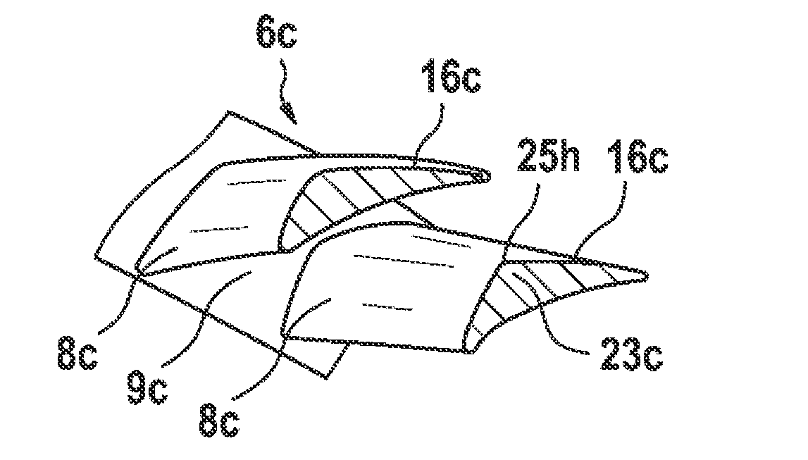
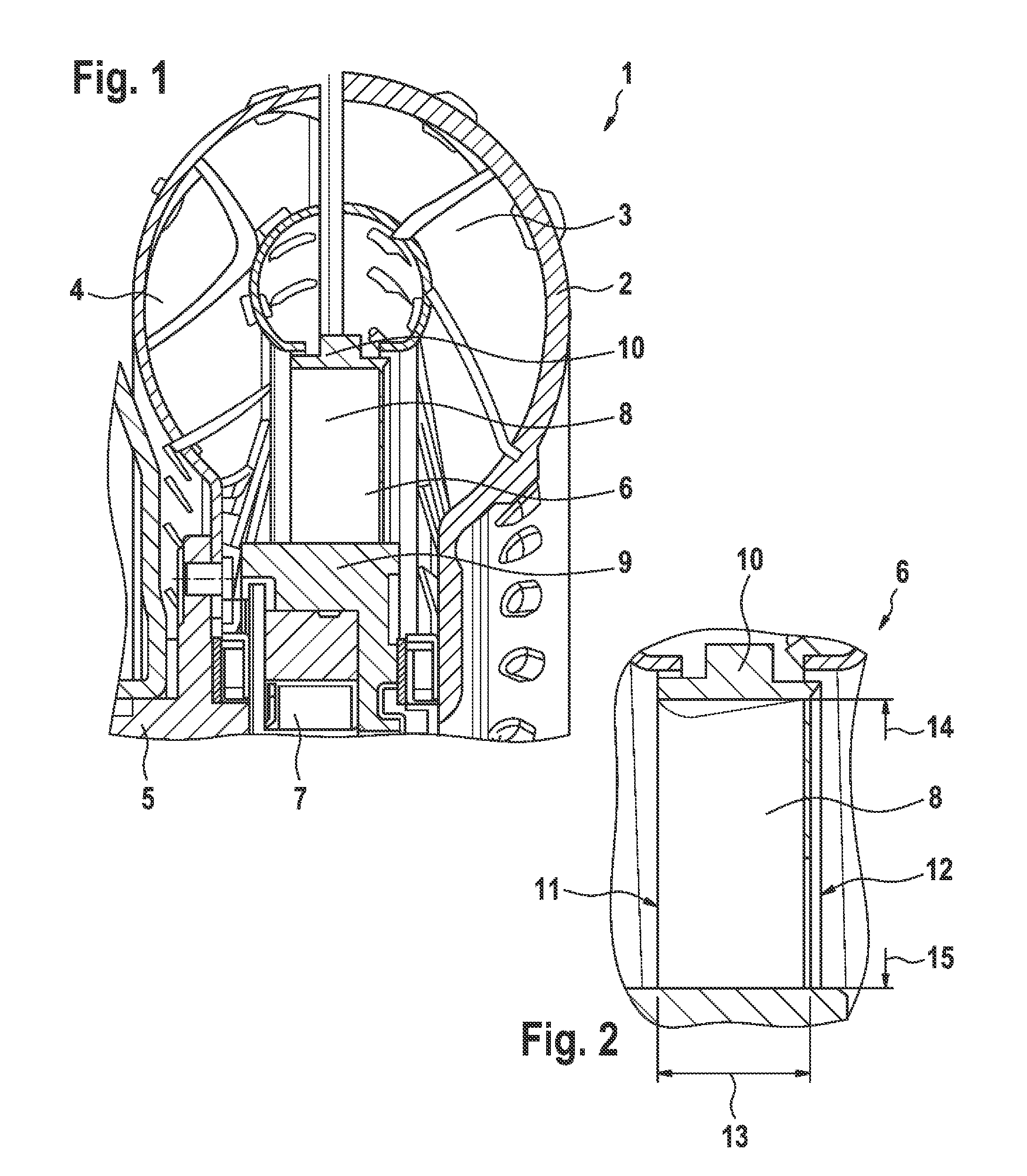
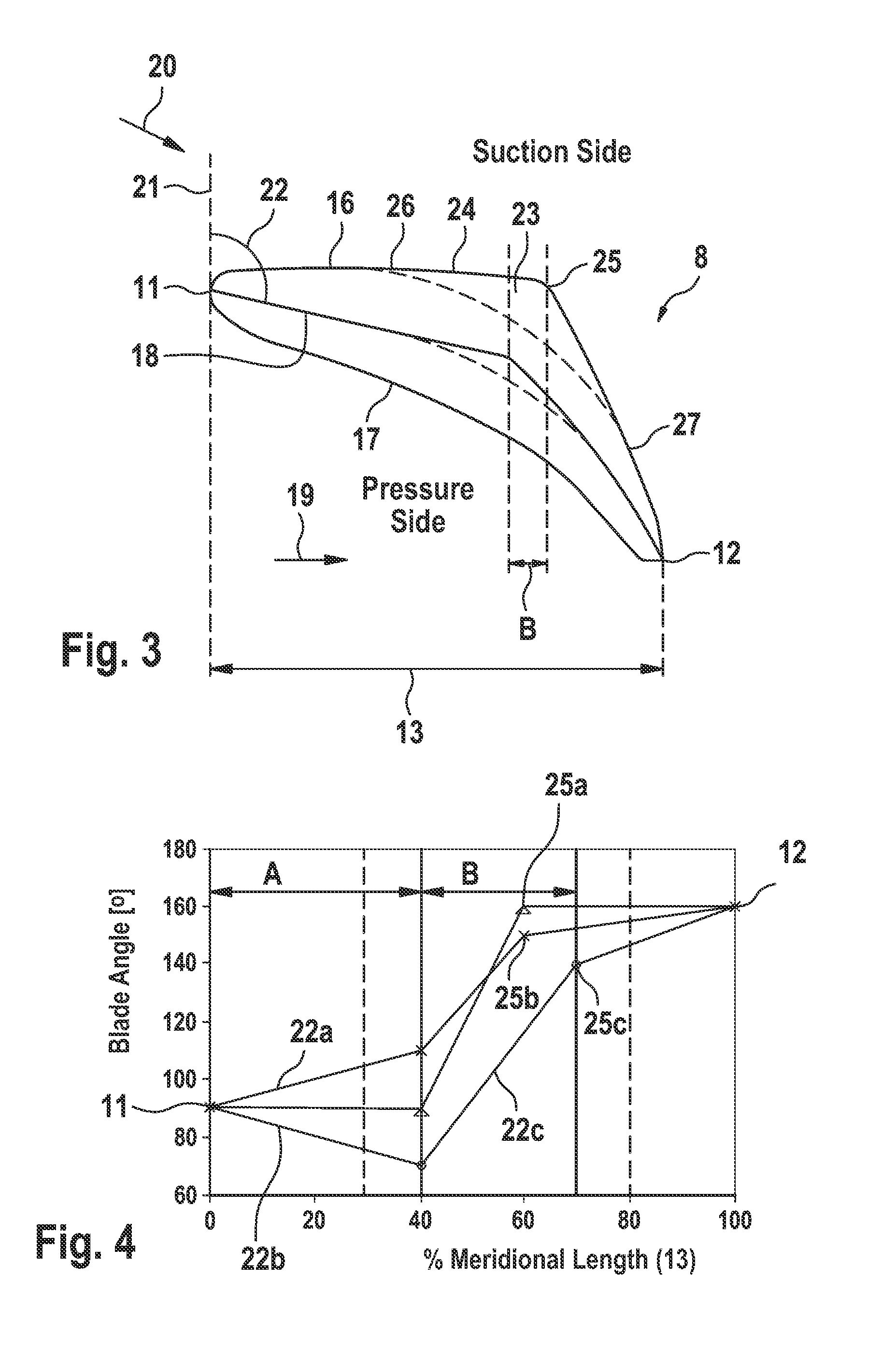
A hydrodynamic torque converter with a pump, a turbine and a stator, having an increased thickness on the suction side of blade profiles of blades in the stator relative to the pressure side of the blades, in order to reduce the pump torque of the torque converter at low to medium speed ratios without influencing the other features of the characteristic diagram.

Description


Claims


Application Information

Patent Timeline
Owner SCHAEFFLER TECH AG & CO KG
Why Eureka
Try Eureka