Automotive lamp whose light source is a semiconductor light emitting device
a light source and semiconductor technology, applied in vehicle headlamps, transportation and packaging, lighting and heating apparatus, etc., can solve the problems of low semiconductor light emitting device luminance efficiency, inability to efficiently diffuse heat produced by semiconductor light emitting device, and inability to easily propagate heat in the stacking direction of core materials. to achieve the effect of efficiently diffusing hea
- Summary
- Abstract
- Description
- Claims
- Application Information
AI Technical Summary
Benefits of technology
Problems solved by technology
Method used
Image

Examples
first embodiment
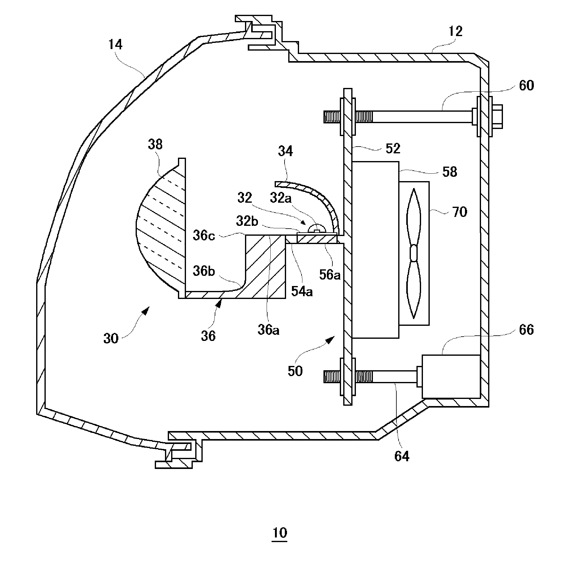
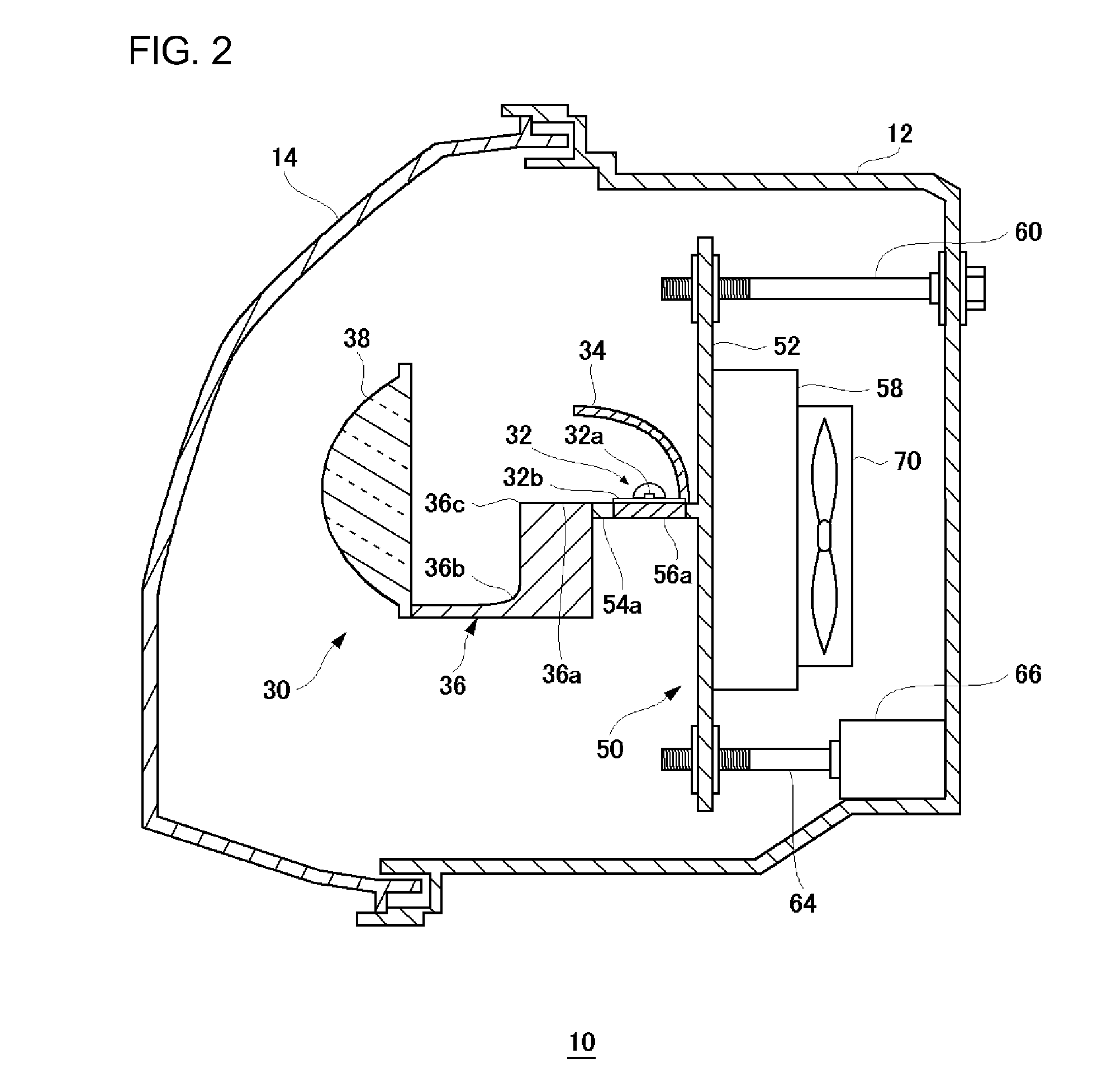
[0026]The present embodiment relates to an automotive lamp comprising a semiconductor light emitting device used as a light source, and a support member that supports the semiconductor light emitting device. In the automotive lamp according to the present embodiment, the supporting member includes a first heat-transfer member by which to diffuse heat produced by the semiconductor light emitting device, and a second heat-transfer member, having an anisotropic thermal conductivity, disposed in contact with the first heat-transfer member. The first heat-transfer member diffuses the heat of the semiconductor light emitting device in a direction where the heat produced by the semiconductor light emitting device is not easily diffused due to the anisotropic thermal conductivity of the second heat-transfer member. As a result, the heat produced by the semiconductor light emitting device is diffused efficiently.
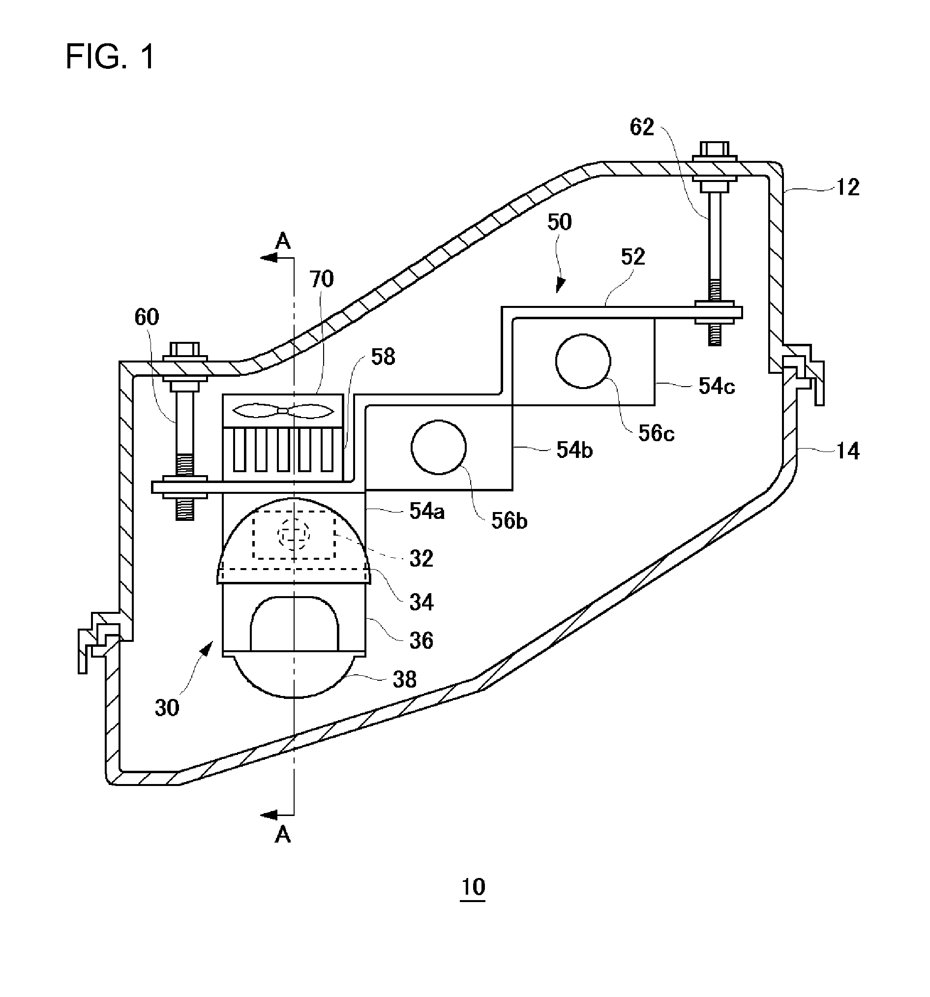
[0027]FIG. 1 is a schematic horizontal cross-sectional view of an automotive lamp a
first modification
[0056]FIGS. 6A and 6B are schematic illustrations to explain a first modification of the first embodiment. FIG. 6A is a schematic illustration of a bracket, whereas FIG. 6B shows a state where a heat radiation fin and a lamp unit 30 are mounted on the bracket. FIG. 7 is a schematic vertical cross-sectional view of an automotive lamp according to the first modification of the first embodiment.
[0057]As shown in FIGS. 6A and 6B and FIG. 7, a bracket 150 of the automotive lamp 10 according to the first modification comprises an approximately plate-like body 152 and light source mounting parts 154a to 154c, protruded from one face of the body 152, which has a surface along a protruding direction on which the semiconductor light emitting device 32 is each mounted. The body 152 has screw holes 151 at predetermined peripheral positions thereof. The bracket 150 is fit to a lamp body 12 in a manner such that the screw holes 151 are engaged and screwed with aiming screws 60 and 62 (see FIG. 1) an
second modification
[0061]FIGS. 8A and 8B are schematic illustrations to explain a second modification of the first embodiment. FIG. 8A is a schematic illustration of a bracket, whereas FIG. 8B is a horizontal cross-sectional view of a bracket. Note that the screw holes used to mount a bracket 350 on the lamp body 12 and the heat radiation fin are omitted in FIGS. 8A and 8B.
[0062]As shown in FIGS. 8A and 8B, a bracket 350 of the automotive lamp 10 according to the second modification comprises an approximately plate-like body 352 and light source mounting parts 354a to 354c, protruded from one face of the body 352, which has a surface along a protruding direction on which the semiconductor light emitting device 32 is each mounted. In the bracket 350, as viewed in a horizontal cross-section, the body 352 is tilted to mounting surfaces 357a to 357c of the lamp unit in the light source mounting parts 354a to 354c. Accordingly, the body 352 is structured such that the body 352 is slanted greatly in the direct
PUM
 Abstract
Description
Claims
Application Information
 - R&D Engineer
- R&D Manager
- IP Professional
- Industry Leading Data Capabilities
- Powerful AI technology
- Patent DNA Extraction
Browse by: Latest US Patents, China's latest patents, Technical Efficacy Thesaurus, Application Domain, Technology Topic.
© 2024 PatSnap. All rights reserved.Legal|Privacy policy|Modern Slavery Act Transparency Statement|Sitemap