Electrostatically atomizing device

a technology of atomizing device and atomizing chamber, which is applied in the direction of air humidification system, lighting and heating apparatus, heating types, etc., can solve the problems of inefficiency in discharging the mist generated in the atomizing barrel outward, and difficulty in efficiently discharging the mist out of the outlet port, so as to reduce the turbulent flow, efficiently discharging the mist out of the housing, and reducing the effect of turbulent flow

Inactive Publication Date: 2010-06-03
PANASONIC CORP
View PDF3 Cites 7 Cited by
  • Summary
  • Abstract
  • Description
  • Claims
  • Application Information

AI Technical Summary

Benefits of technology

This patented design allows for better control over how much liquid droplets (mist) get mixed together inside the atomizer's cylindrical space while still being able to smoothly exit outside due to gravity forces caused by the rotation of the spray nozzle during use. Additionally, the system includes multiple air supply channels located close enough around the atomization rod to ensure even distribution of gas throughout the entire volume where they come up against the inner walls of the device. Overall, these technical features improve the efficiency and effectiveness of the fluid-spitting process described above.

Problems solved by technology

This patented technical problem addressed in this patents relates to improving efficient removal or prevention of condensations inside the atomizer's chamber during use due to leakage of moisture outside when introducing cold liquid onto the emitting element.

Method used


Image

  • Electrostatically atomizing device
  • Electrostatically atomizing device
  • Electrostatically atomizing device

Examples


Embodiment Construction

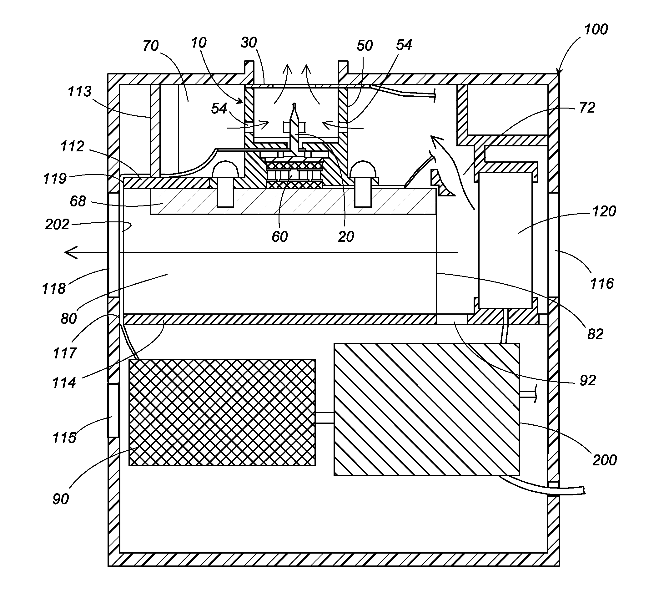
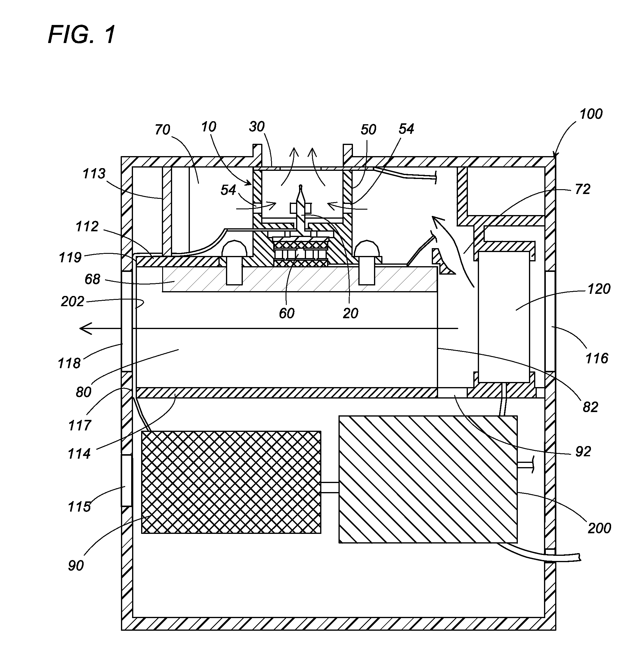
[0018]An electrostatically atomizing device in accordance with a first embodiment of the present invention is explained with reference to the attached drawings. As shown in FIG. 1, the electrostatically atomizing device includes an electrostatically atomizing unit 10 and a housing 100 which accommodates the unit. The housing 100 has, as shown in FIG. 4, a casing body 101 and a casing cap 102 which covers one side of the casing body 101.

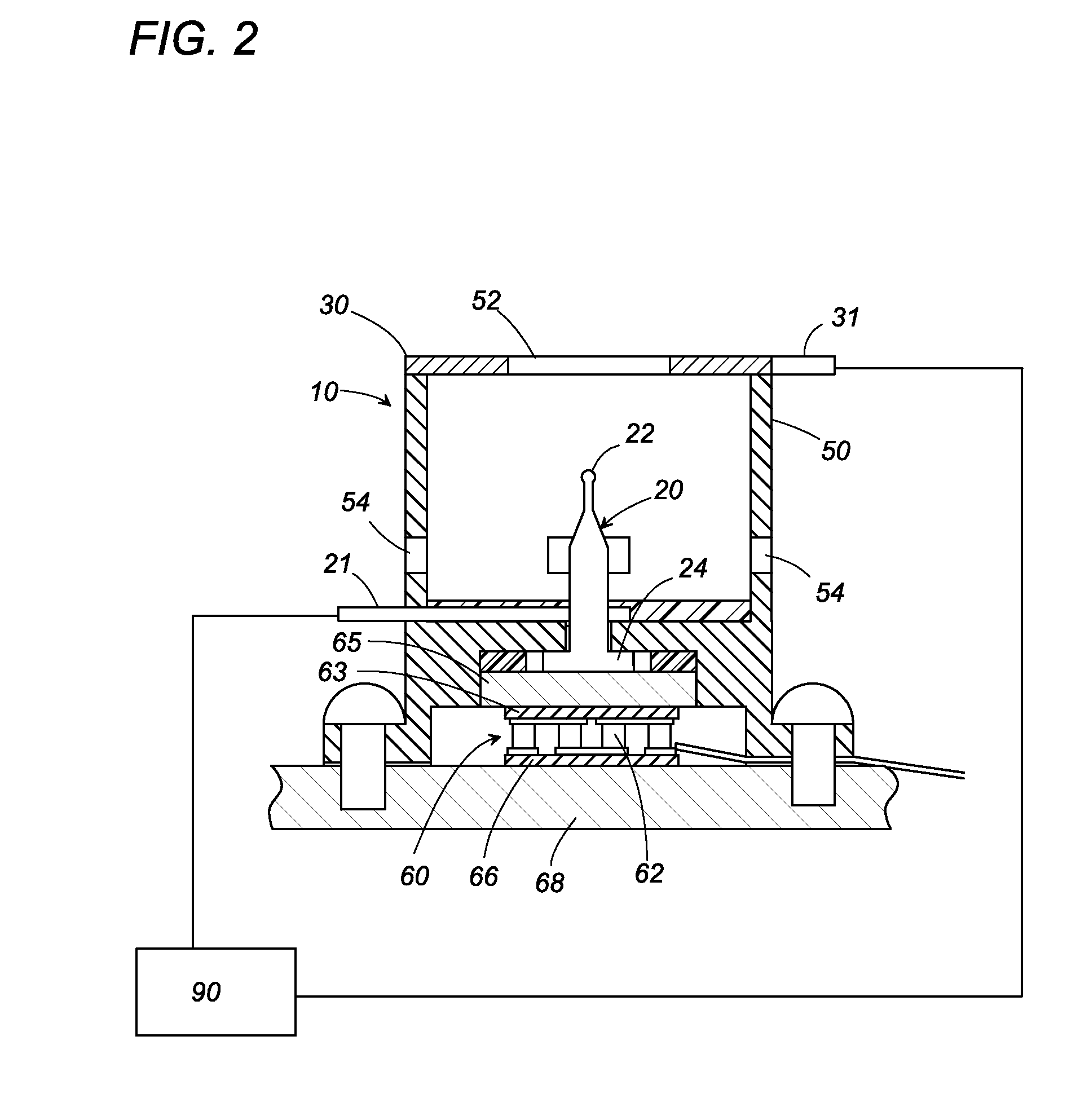
[0019]As best shown in FIG. 2, the electrostatically atomizing unit 10 includes an emitter electrode 20, an opposed electrode 30, and an atomizing barrel 50 which carries a heat exchanger 40. The emitter electrode 20 is disposed on a central axis of the atomizing barrel 50, and has its rear end fixed to a bottom face 51 of the atomizing barrel 50 so as to project its tip within the atomizing barrel 50. The opposed electrode 30 is configured into a ring shape having a circular window in its center, and is fixed to the front end of the atomizing barrel 50


PUM


Abstract

An electrostatically atomizing device has a housing and an electrostatically atomizing unit accommodated within the housing. The electrostatically atomizing unit includes an atomizing barrel and an emitter electrode disposed within the atomizing barrel and is configured to atomize water supplied to the emitter electrode at a tip of the emitter electrode and generate mist of charged minute water particles. Formed within the housing is an air pressure chamber which surrounds the atomizing barrel. The atomizing barrel is formed in its peripheral wall with a plurality of air inlets which are arranged circumferentially around the atomizing barrel to introduce pressurized air from the air pressure chamber for carrying the mist on the pressurized air introduced into the atomizing barrel from the plural air inlets and discharging the mist outwardly of the housing.

Description


Claims


Application Information

Patent Timeline
Owner PANASONIC CORP
Why Eureka
Try Eureka