Coil device and method for manufacturing same

Active Publication Date: 2010-09-02
SHT CO LTD
View PDF5 Cites 3 Cited by
  • Summary
  • Abstract
  • Description
  • Claims
  • Application Information

AI Technical Summary

Benefits of technology

[0022]According to the present invention, in a manufacturing method of a coil device which employs a conductive wire having a cross-sectional shape with a height dimension greater than a width dimension to form a coil, by employing a simple step of only winding the conductive wire around an outer peripheral surface of a core with a tip end part of the conductive wire to be one lead part twisted, subsequent formation of the lead part can be performed easily.

Problems solved by technology

However, in the manufacturing method shown in FIG. 26, a rotational drive mechanism to wind the air core coil C around the ring-like core D as shown in FIG. 26(c) is complicated, and moreover, if transformation of the one end of the air core coil C exceeds an elastic deformation limit, subsequent winding step becomes extremely difficult.

Method used


Image

  • Coil device and method for manufacturing same
  • Coil device and method for manufacturing same
  • Coil device and method for manufacturing same

Examples


Example

EXPLANATION OF REFERENCE NUMERALS

[0049]1 core

[0050]11 rib

[0051]2 coil

[0052]21 conductive wire

[0053]22 winding portion

[0054]3 twist part

[0055]4 lead part

[0056]5 lead part

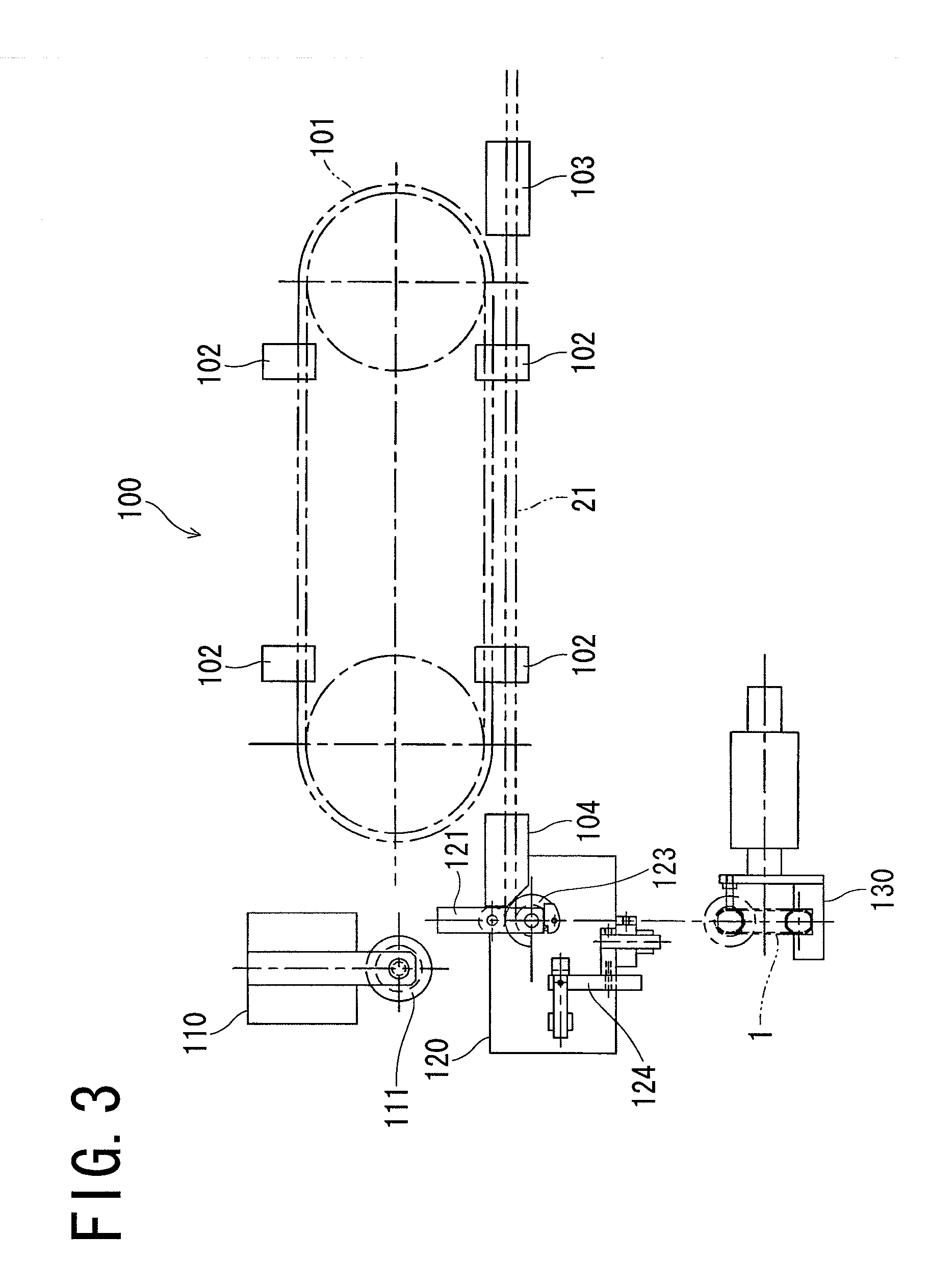
[0057]100 conductive wire feeding device

[0058]110 forming device

[0059]120 tip end part forming device

[0060]130 core holding device

[0061]140 conductive wire folding mechanism

BEST MODE FOR CARRYING OUT THE INVENTION

[0062]An embodiment of the present invention is to be described in detail below with reference to the drawings.

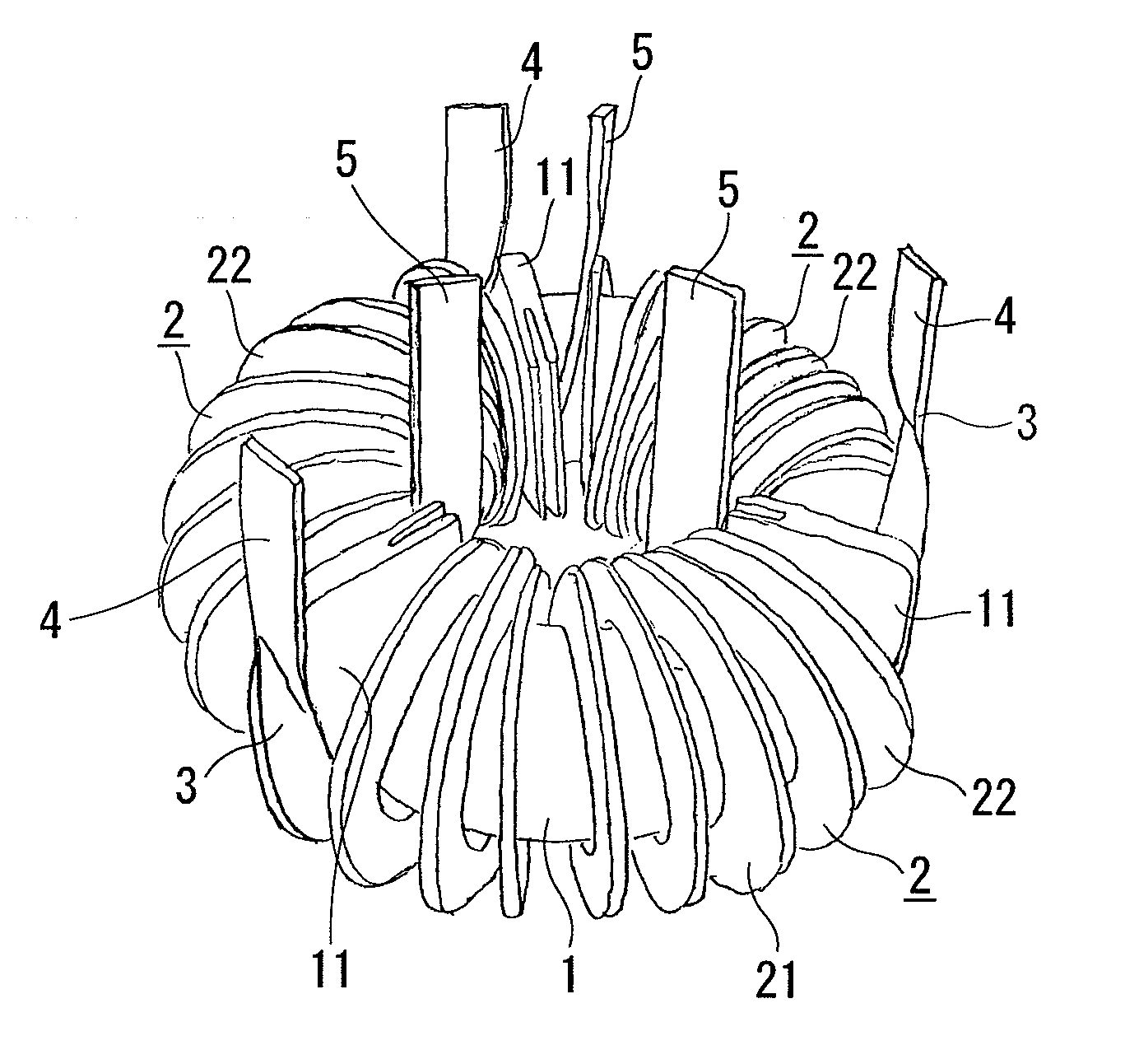
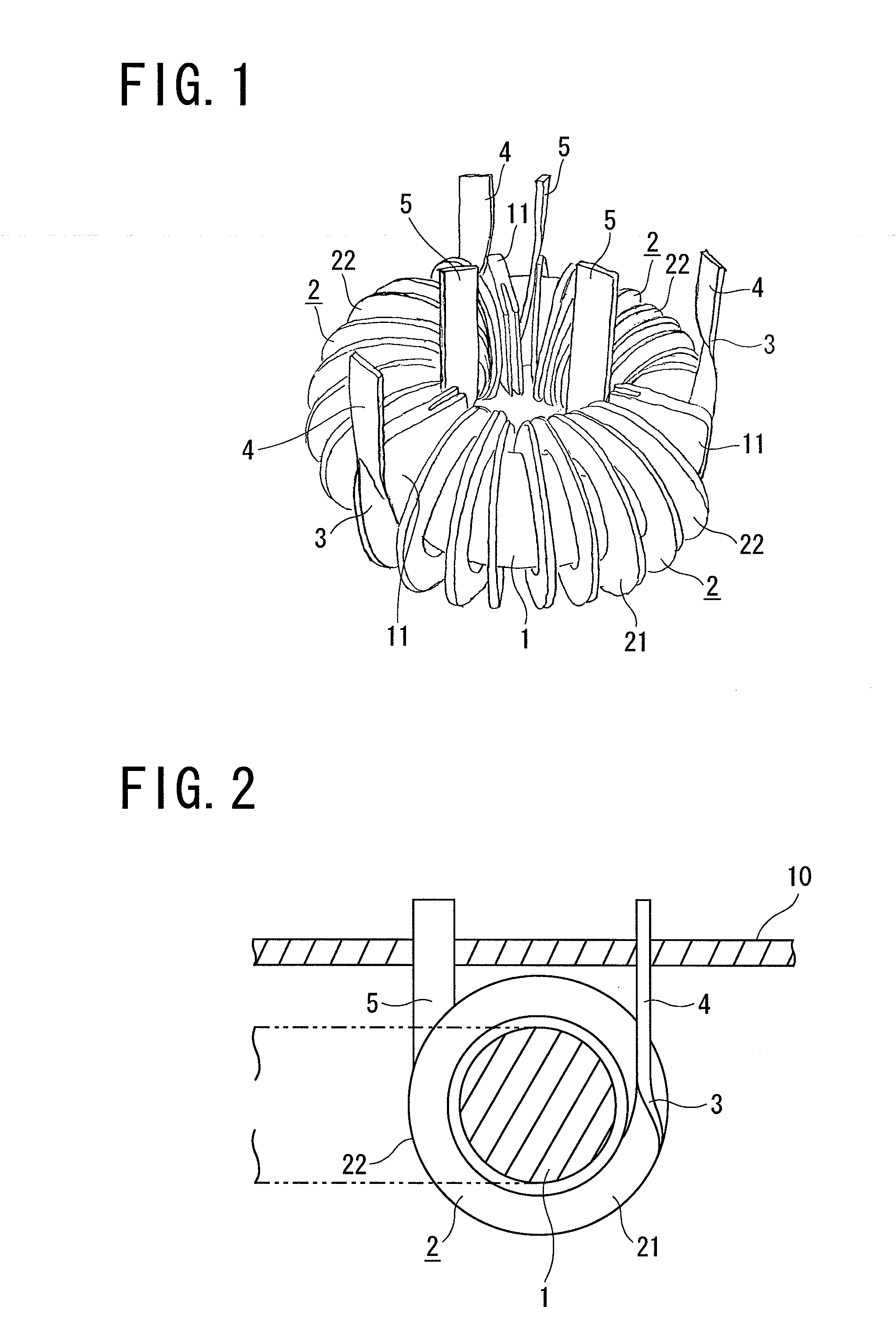
[0063]A coil device according to the present invention comprises a ring-like core 1 and three coils 2, 2, 2 wound around the core 1 as shown in FIG. 1. A three-phase alternating current is supplied to the three coils 2, 2, 2.

[0064]Specifically, the core 1 comprises a ring-like magnetic core covered by a covering layer made of synthetic resin, and three ribs 11, 11, 11 project with a phase difference of 120 degrees on an outer peripheral surface of the core 1. Three winding areas are thereby formed, and


PUM

PropertyMeasurementUnit
Angleaaaaaaaaaa
Electrical conductoraaaaaaaaaa
Areaaaaaaaaaaa

Abstract

A method for manufacturing a coil device comprises a first step of twisting a tip end part of the conductive wire by approximately 90 degrees with respect to a conductive wire portion arranged rearward continuously from the tip end part to form a twist part, and winding the tip end part of the conductive wire around the outer peripheral surface of the core in a lying posture on the outer peripheral surface; a second step of winding the conductive wire arranged rearward continuously from the twist part around the outer periphery surface of the core in a standing posture on the outer peripheral surface; and a third step of transforming the conductive wire on a tip end side with respect to the twist part in a direction apart from the outer periphery surface of the core to form one lead part extending substantially linearly.

Description


Claims


Application Information

Patent Timeline
Owner SHT CO LTD
Why Eureka
Try Eureka