Auxiliary power device of bicycle

Inactive Publication Date: 2010-09-02
YONGMART MFG
View PDF0 Cites 3 Cited by
  • Summary
  • Abstract
  • Description
  • Claims
  • Application Information

AI Technical Summary

Benefits of technology

[0006]The primary objective of the present invention is to provide an auxiliary power device of a bicycle,

Problems solved by technology

In early time, bicycles are nothing but a cheap transportation.
However, cycling in mountain roads or cycling for a long distance still is a heavy loading f

Method used


Image

  • Auxiliary power device of bicycle
  • Auxiliary power device of bicycle
  • Auxiliary power device of bicycle

Examples


Embodiment Construction

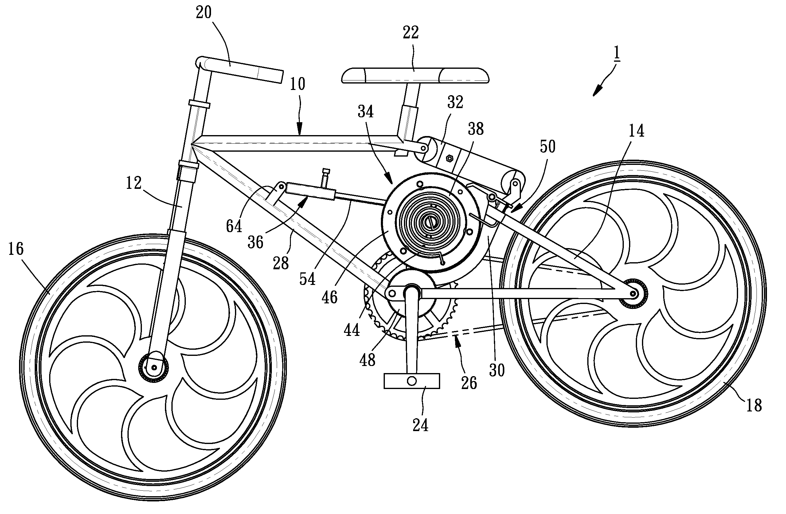
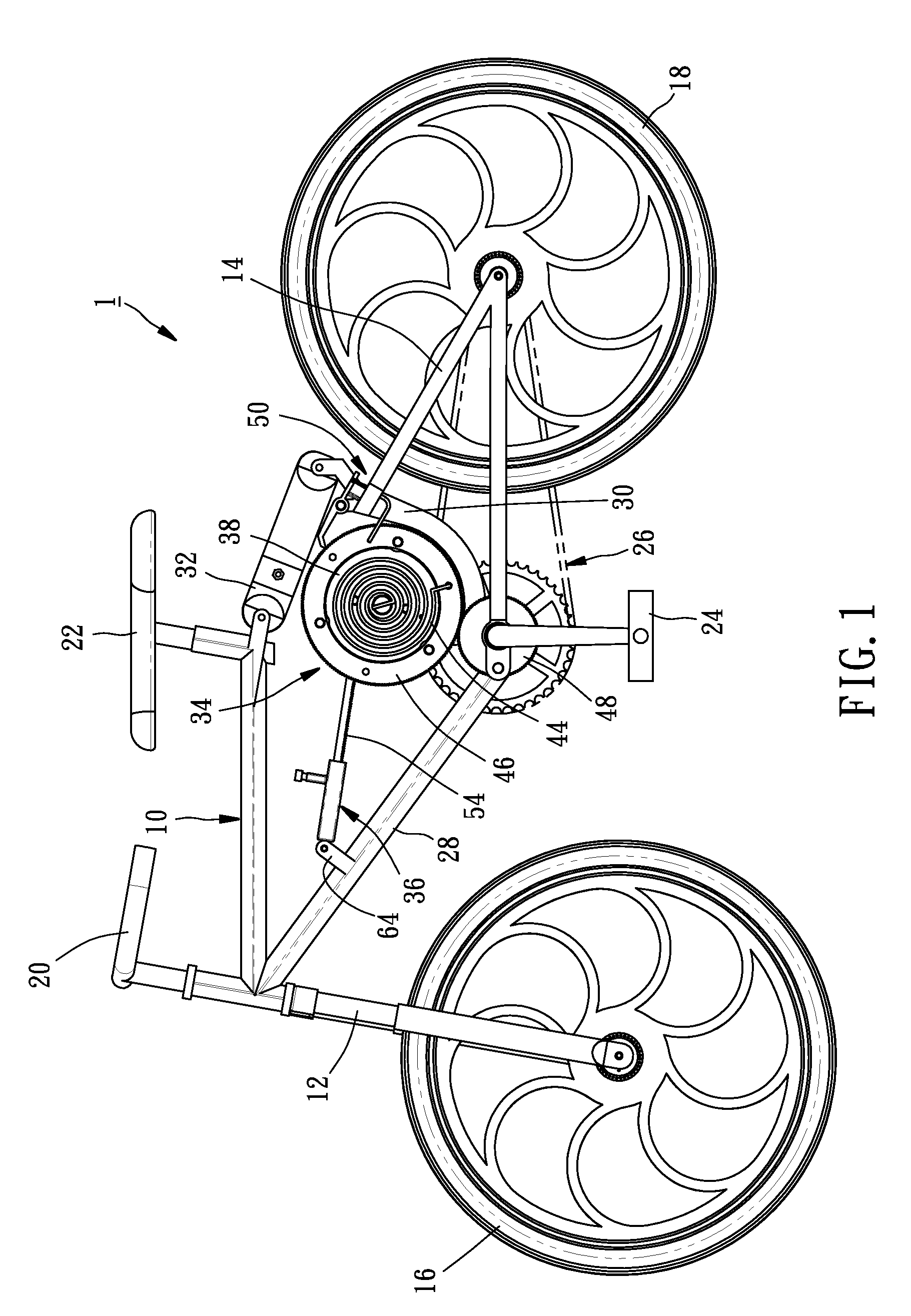
[0015]As shown in FIG. 1, a bicycle 1 of the first preferred embodiment of the present invention includes a frame 10 having a front fork 12, a rear fork 14, and two wheels 16, 18 pivoted on the front fork 12 and the rear fork 14 respectively. The frame 10 further includes a handle bar 20 connecting the front fork 12, a seat 22, a crank 24, and a transmission assembly 26 including a front gear set connecting the crank 24, a rear gear set on the rear wheel 18, and a chain connecting the front gear set and the rear gear set. The aforesaid elements are as same as the conventional bicycle, so we do not describe the detail here.

[0016]The frame 10 includes a first section 28 and a second section 30. A cushion 32 is provided between the first section 28 and the second section 30 that the first section 28 and the second section 30 will have a relative motion therebetween in cycling. The present invention uses such relative motion between the first section 28 and the second section 30 to generat


PUM


Abstract

An auxiliary power device of a bicycle includes a driving member and a base member provided at a first section and a second section of the bicycle respectively. The first section and the second section are two parts of the bicycle, which has a relative motion therebetween in cycling. An input member is provided to the base member to be driven by the driving member when the first section moves relative to the second section. The input member turns a power storage member to store a power. A control member is provided for manipulation to release the power stored in the power storage member for moving the bicycle forward.

Description


Claims


Application Information

Patent Timeline
Owner YONGMART MFG
Why Eureka
Try Eureka