Electronic device that can detect and report tampering

a technology of electronic devices and tampering detection, applied in emergency power supply arrangements, casings/cabinets/drawers, electric apparatus casings/cabinets/drawers, etc., can solve the problems of increasing the complexity of installing such electronic devices, increasing the size or etc., to reduce the size and manufacturing cost of electronic devices, reduce the effect of battery power consumption and small siz

Active Publication Date: 2020-04-16
SERCOMM
View PDF0 Cites 0 Cited by
  • Summary
  • Abstract
  • Description
  • Claims
  • Application Information

AI Technical Summary

Benefits of technology

The invention relates to integrating two different types of electrical devices together into one unit that reduces their overall dimensions but still allows for easy installation without unnecessary energy usage when needed. This makes them smaller than traditional batteries used by IoT technology or other similar products.

Problems solved by technology

The technical problem addressed in this patented text relates how to prevent unauthorized access by an electronics device that can be easily opened without being detected beforehand during installation on its owners' premises.

Method used


Image

  • Electronic device that can detect and report tampering
  • Electronic device that can detect and report tampering
  • Electronic device that can detect and report tampering

Examples


Embodiment Construction

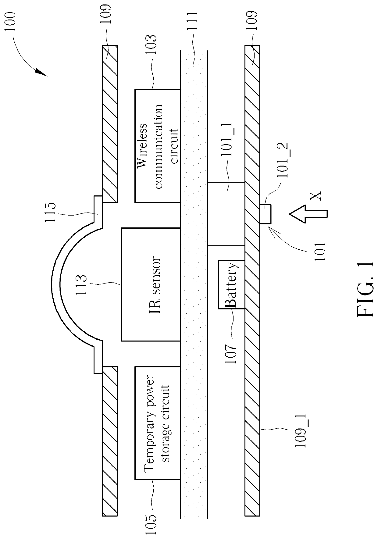
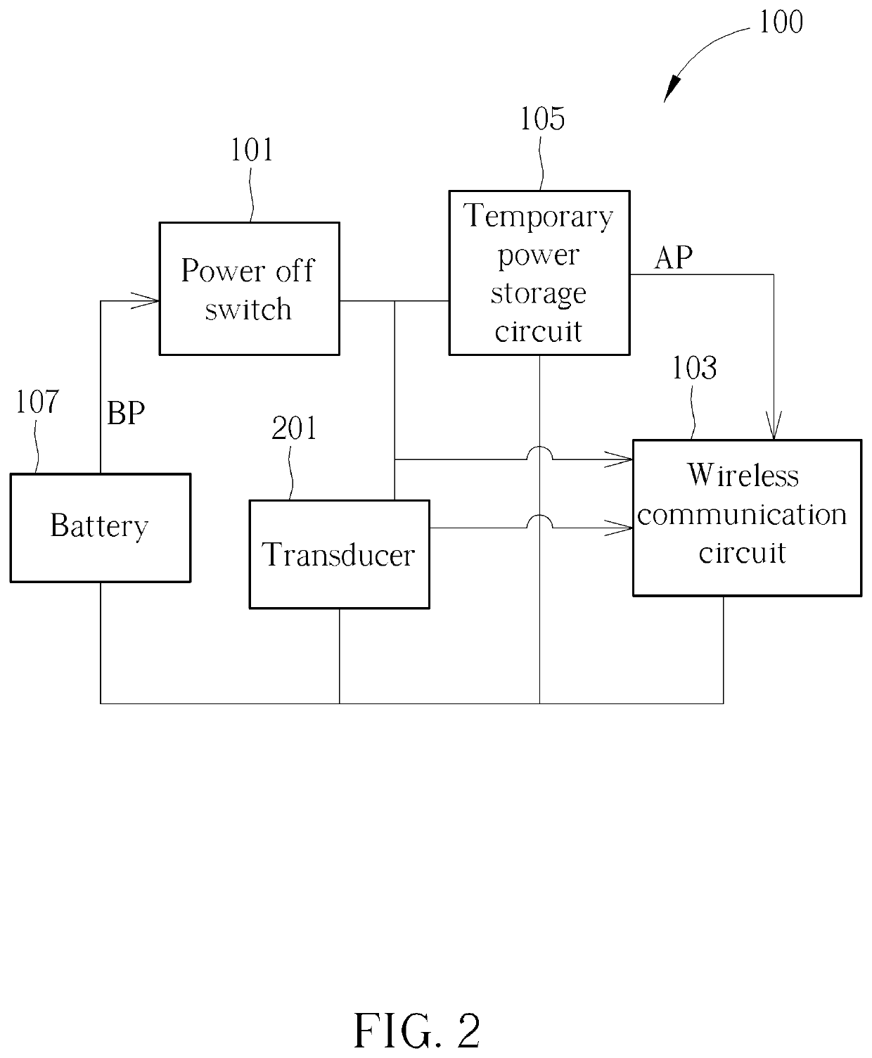
[0013]In following descriptions, a plurality of embodiments are provided to explain the concept of the present invention. Please note, each component in following embodiments can be implemented by hardware (e.g. device, circuit) or hardware with software (e.g. a processor with at least one program).

[0014]FIG. 1 is a schematic diagram illustrating an internal structure of an electronic device according to one embodiment of the present invention. FIG. 2 is a block diagram illustrating an electronic device according to one embodiment of the present invention, which illustrates electrical connections between each component. Please refer to FIG. 1 and FIG. 2 to understand the concept of the present invention. Please note, the arrangements illustrated in FIG. 1 and FIG. 2 are only for examples and do not mean to limit the scope of the present application, any arrangement that can reach the same function should fall in the scope of the present invention.

[0015]As illustrated in FIG. 1 and FIG.


PUM


Abstract

An electronic device that can detect and report tampering, comprising: a case, comprising an installation surface, wherein the electronic device is for being installed to an installation position via the installation surface; a battery, located inside the case, configured to provide battery power; a temporary power storage circuit, located in the case; a power off switch, located on the case and coupled between the battery and the temporary power storage circuit, configured to operate in a conductive state while the electronic device is installed at the installation position, and configured to automatically operate in a power off state after the electronic device being removed from the installation position; and a wireless communication circuit, located in the case and coupled to the power off switch and the temporary power storage circuit.

Description


Claims


Application Information

Patent Timeline
Owner SERCOMM
Why Eureka
Try Eureka