Linear compressor

a compressor and linear technology, applied in the direction of piston pumps, positive displacement liquid engines, pump components, etc., can solve the problems of low operation reliability and large mechanical loss caused by motion conversion, and achieve the effects of reducing deformation of cylinders, reducing frame size, and increasing cylinder siz

Active Publication Date: 2010-10-14
LG ELECTRONICS INC
View PDF9 Cites 19 Cited by
  • Summary
  • Abstract
  • Description
  • Claims
  • Application Information

AI Technical Summary

Benefits of technology

The present invention relates to a linear compressor that improves its performance by reducing stress on the frame and cylinders during compression. This results in improved durability without compromising the efficiency or accuracy of the pumping process.

Problems solved by technology

This patent describes a technical problem addressed in this patent text relating to improving the performance and durability of linear compressors. Specifically, traditional linear compressors have issues with high stress and strain caused by the linear movement of the pistons. To address these issues, the inventive design uses a linear compressor with a linear actuator and a linear compressor system that allows for independent adjustment of each part of the compressor's operating parameters. However, current designs require a separate housing for each part of the compressor, leading to higher costs and complexity.

Method used


Image

  • Linear compressor
  • Linear compressor
  • Linear compressor

Examples


Embodiment Construction

[0031]Hereinafter, preferred embodiments of the present invention will be described in detail with reference to the accompanying drawings.

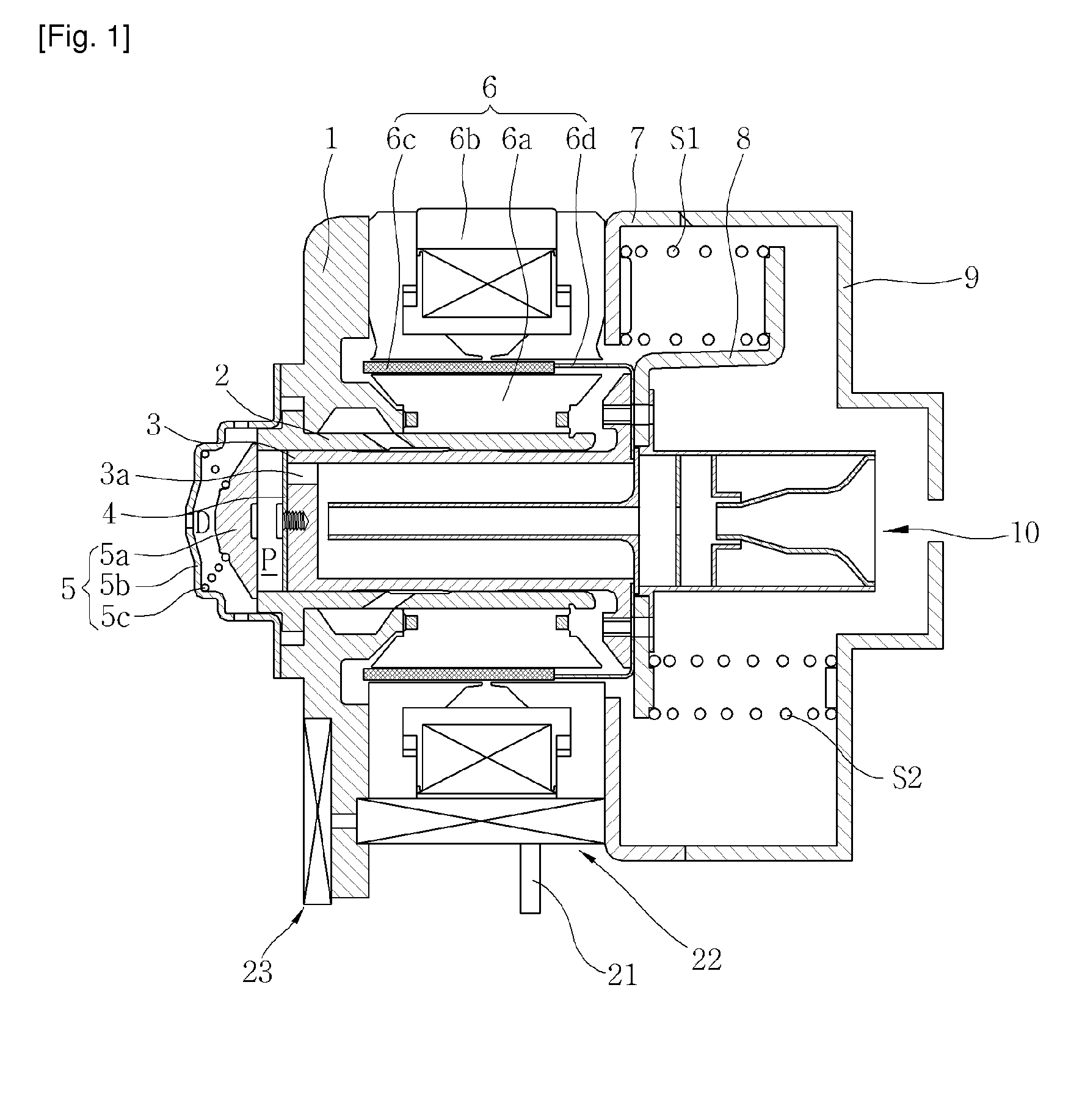
[0032]FIG. 5 is a view illustrating a linear compressor according to an embodiment of the present invention. The linear compressor 100 according to the present invention includes a cylinder 200, a piston 300, a linear motor 400 composed of an inner stator 420, an outer stator 440 and a permanent magnet 460, and an oil supply assembly 900 inside a shell 110 which is a hermetic container. When the permanent magnet 460 is linearly reciprocated between the inner stator 420 and the outer stator 440 due to a mutual electromagnetic force, the piston 300 connected to the permanent magnet 460 is linearly reciprocated together with the permanent magnet 460, and oil stored in the bottom of the shell 110 is pumped / supplied through the oil supply assembly 900 due to vibration of the piston 300 to thereby lubricate the cylinder 200 and the piston 300.

[0033]The i


PUM


Abstract

The present invention provides a linear compressor, including: a cylinder having a compression space of refrigerant therein; a piston linearly reciprocated inside the cylinder in an axis direction to compress the refrigerant; and a frame having a mounting hole so that one end of the cylinder can be mounted thereon, and also having a deformation prevention portion in some section around the mounting hole brought into contact with the one end of the cylinder. Even though the size of the cylinder is increased and the size of the frame is limited, the frame is provided with enough strength to support the cylinder, thereby reducing fastening deformations and improving operation reliability.

Description


Claims


Application Information

Patent Timeline
Owner LG ELECTRONICS INC
Why Eureka
Try Eureka