Apparatus for feeding foil of printing machine with tension

a technology of printing machine and foil, applied in printing presses, embossing decorations, printing, etc., can solve the problems of waste of processing material f, achieve the effect of preventing foil damage, high speed, and easy adjustment of tension applied

Inactive Publication Date: 2010-11-25
SONG BYUNG JUN
View PDF7 Cites 2 Cited by
  • Summary
  • Abstract
  • Description
  • Claims
  • Application Information

AI Technical Summary

Benefits of technology

The present invention provides an apparatus that allows for easy adjustment of the tension on a printing foil during printing without causing damage or affecting its effectiveness at high speeds.

Problems solved by technology

The technical problem addressed in this patent is how to efficiently use processing materials during foil printing without wasteful consumption.

Method used


Image

  • Apparatus for feeding foil of printing machine with tension
  • Apparatus for feeding foil of printing machine with tension
  • Apparatus for feeding foil of printing machine with tension

Examples


Embodiment Construction

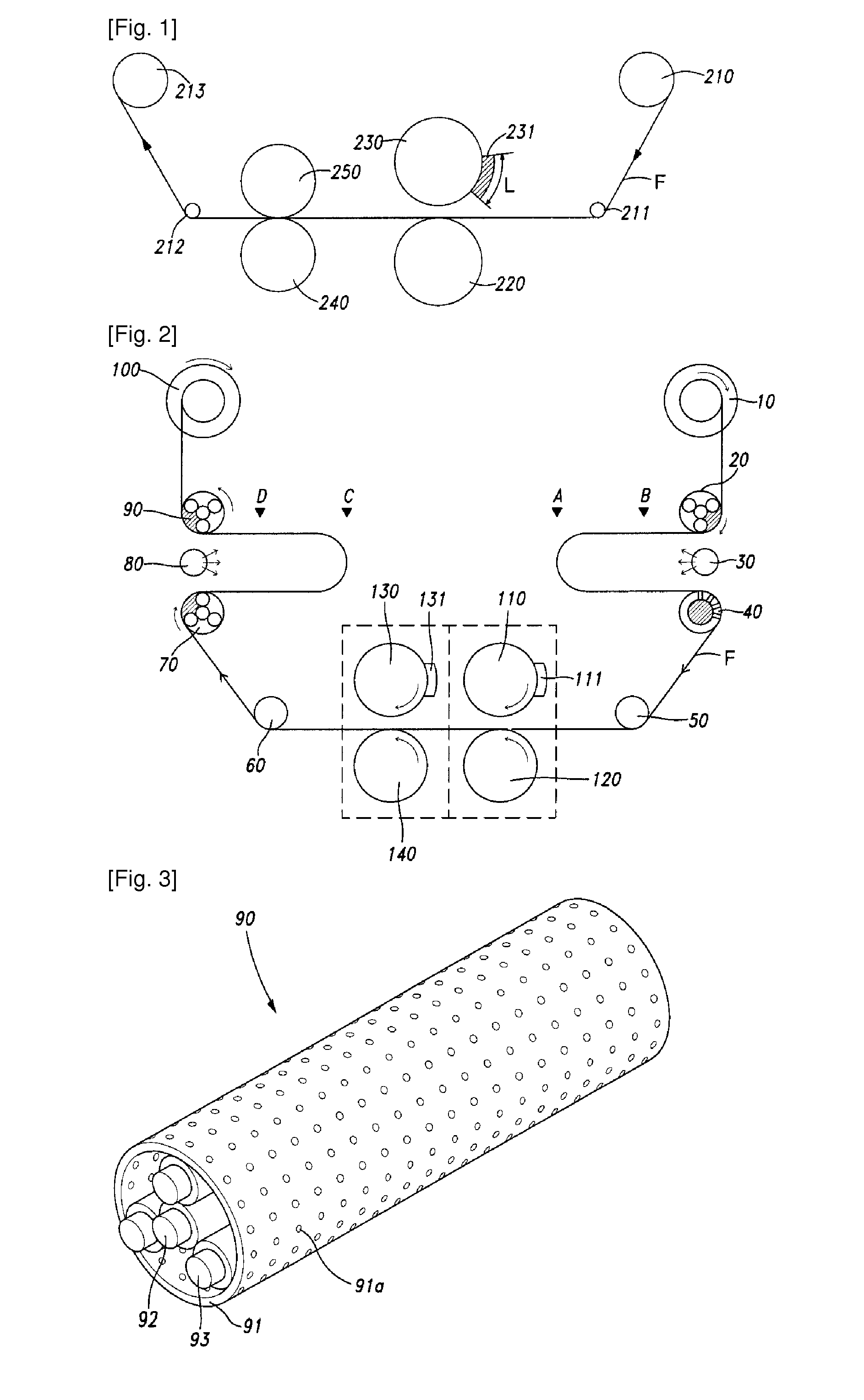
[0022]FIG. 2 is a schematic view illustrating a printing machine according to the present invention. As shown, a foil F wound in a storage reel 10 is unwound as a storage reel 10 is rotated. The unwound foil F moves to a blower 30 in accordance with guide of a tension adjustment shaft 20. The foil F, which has passed through the tension adjustment shaft 20, is blown by compressed air of the blower 30 at a given length. The foil, which has passed through the blower 30, passes through a suction shaft 40 and then reaches a printing part marked with a dotted line. In the printing part, a die 111 of an impression roller 110 performs printing while the impression roller 110 is rotated in a state that it is engaged with a lower roller 120. Feed rollers 130 and 140 at the rear of the printing part are rotated by being synchronized with the impression roller 110. A die 131 of the feed roller 130 has an arc greater than that of a die 111 of the impression roller 110, and moves the foil F without


PUM


Abstract

An apparatus for feeding a foil of a printing machine with tension is disclosed, in which vacuum pressure is only applied to a part of a shaft through which a foil passes, and an outer surface in contact with the foil is rotated. The apparatus comprises a cylindrical shaft body provided with a plurality of holes on the outer surface; a sun roller provided based on the center of the shaft body, having a diameter smaller than an inner diameter of the shaft body; a plurality of pinion rollers closely adhered to one another between the sun roller and the inner surface of the shaft body; and a bearing stopper provided to seal both ends of the shaft body and connected with a pump to supply vacuum pressure to only a space formed by the shaft body, the sun roller and two of the pinion rollers.

Description


Claims


Application Information

Patent Timeline
Owner SONG BYUNG JUN
Why Eureka
Try Eureka